764
Data Control Instructions Section 3-18
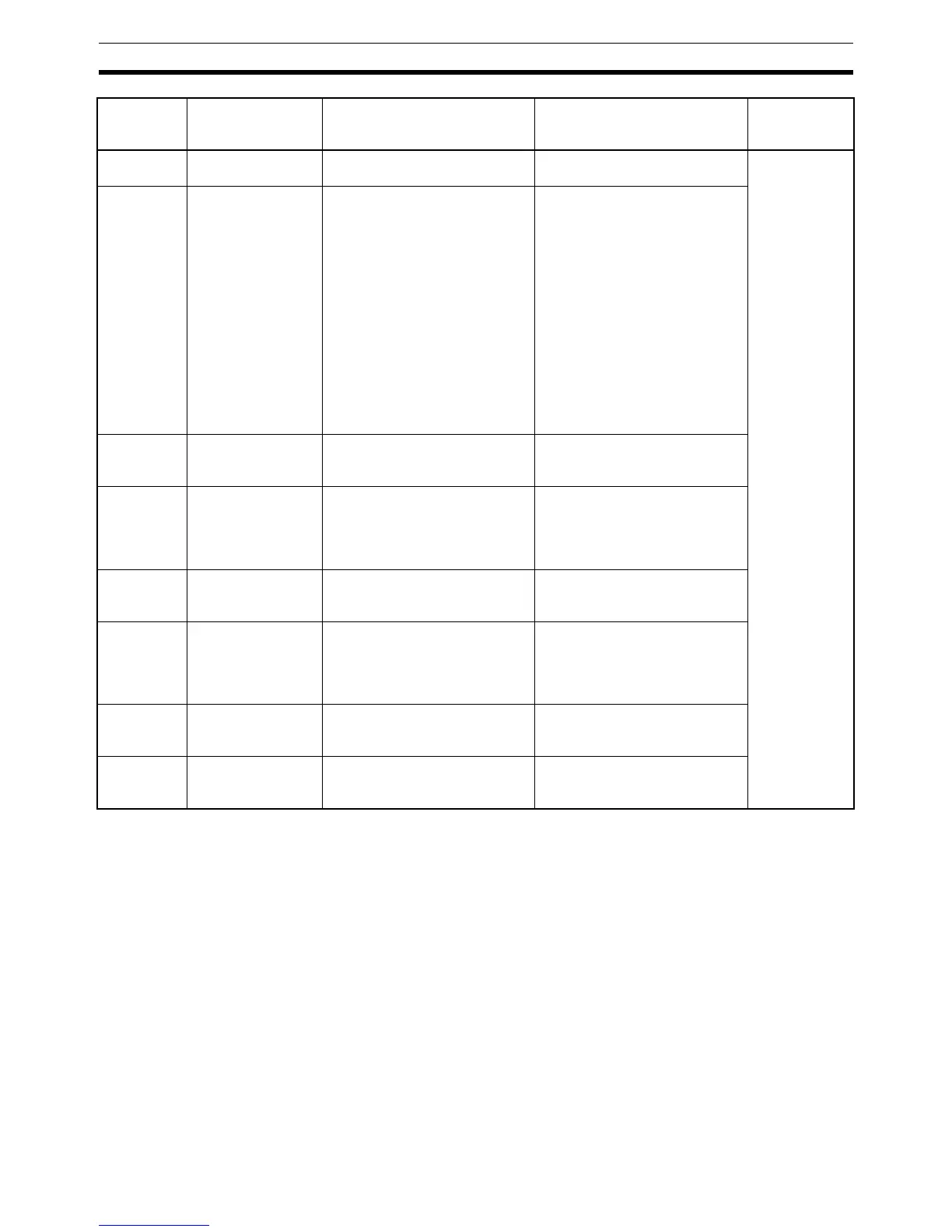
Note 1. When the unit is designated as 1, the range is from 1 to 8,191 times the
period. When the unit is designated as 9, the range is from 0.1 to 819.1 s.
When 9 is designated, set the integral and derivative times to within a
range of 1 to 8,191 times the sampling period.
2. Setting the 2-PID parameter (
α) to 000 yields 0.65, the normal value.
3. When the manipulated variable output limit control is enabled (i.e., set to
“1”), set the values as follows:
0000 ≤ MV output lower limit ≤ MV output upper limit ≤ Max. value of output range
Sampling Period and
Cycle Time
The sampling period can be designated in units of 10 ms (0.01 to 99.99 s), but
the actual PID action is determined by a combination of the sampling period
and the time of PID instruction execution (with each cycle). The relationship
between the sampling period and the cycle time is as follows:
• If the sampling period is less than the cycle time, PID control is executed
with each cycle and not with each sampling period.
Bit 00 of C+5 PID forward/reverse
designation
Determines the direction of the
proportional action.
0: Reverse action
1: Forward action
Not allowed
Bits 13 to 14
of C+6
ID starting integral
manipulated vari-
able designation
(unit version 4.0 or
later only)
Determines the initial integral
manipulated variable when PID
control is started (i.e., when the
input turns ON).
Bit 14 = 0 and bit 13=0:
Start from same integral manipu-
lated value as manipulated vari-
able output designation (Pre-Ver.
4.0 operation).
Bit 14 = 0 or 1 and bit 13 = 1:
Bumpless operation (i.e., start
from an integral manipulated
variable that will not abruptly
change the manipulated vari-
able output and result in a con-
tinuous change).
Bit 14 = 1 and bit 13 = 0:
Start with integral manipulated
variable = 0.
Bit 12 of C+6 Manipulated vari-
able output limit
control
Determines whether or not limit
control will apply to the manipu-
lated variable output.
0: Disabled (no limit control)
1: Enabled (limit control)
Bits 08 to 11
of C+6
Input range The number of input data bits. 0: 8 bits 5: 13 bits
1: 9 bits 6: 14 bits
2: 10 bits 7: 15 bits
3: 11 bits 8: 16 bits
4: 12 bits
Bits 04 to 07
of C+6
Integral and deriva-
tive unit
Determines the unit for express-
ing the integral and derivative
constants.
1: Sampling period multiple
9: Time (unit: 100 ms)
Bits 00 to 03
of C+6
Output range The number of output data bits. 0: 8 bits 5: 13 bits
1: 9 bits 6: 14 bits
2: 10 bits 7: 15 bits
3: 11 bits 8: 16 bits
4: 12 bits
C+7 Manipulated vari-
able output lower
limit
The lower limit for when the
manipulated variable output limit
is enabled.
0000 to FFFF (binary)
(See note 3.)
C+8 Manipulated vari-
able output upper
limit
The upper limit for when the
manipulated variable output limit
is enabled.
0000 to FFFF (binary)
(See note 3.)
Control
data
Item Contents Setting range Change with
ON input
condition