942
Basic I/O Unit Instructions Section 3-23
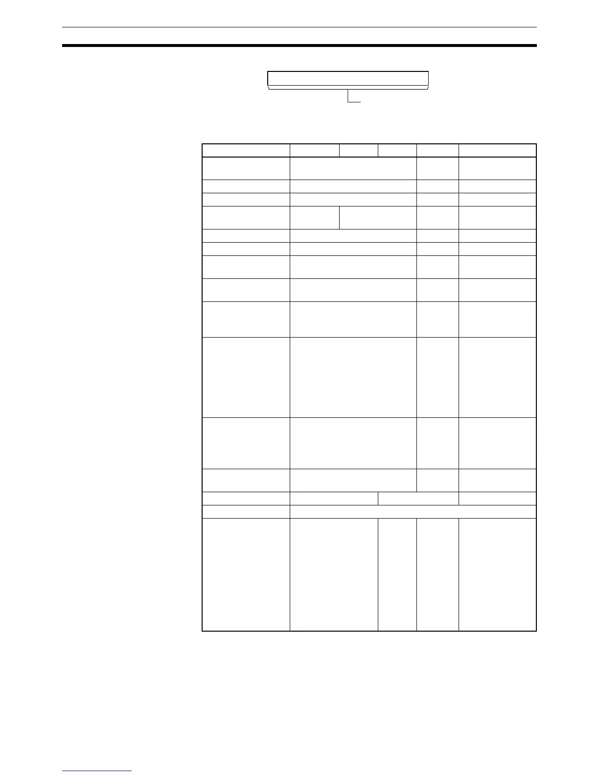
Operand Specifications
Description DSW(210) outputs control signals to bits 00 to 04 of O, reads the specified
number of digits (either 4-digit or 8-digit, specified in C1) of digital switch data
line data from I, and stores the result in D and D+1. (If 4 digits are read, the
result is stored in D. If 8 digits are read, the result is stored in D and D+1.)
C2
15 0
System word
(Cannot be accessed by the user.)
Area I O D C1 C2
CIO Area CIO 0000 to CIO 6143 --- CIO 0000 to
CIO 6143
Work Area W000 to W511 --- W000 to W511
Holding Bit Area H000 to H511 --- H000 to H511
Auxiliary Bit Area A000 to
A959
A448 to A953 --- A448 to A959
Timer Area T0000 to T4095 --- T0000 to T4095
Counter Area C0000 to C4095 --- C0000 to C4095
DM Area D00000 to D32767 --- D00000 to
D32767
EM Area without
bank
E00000 to E32767 --- E00000 to
E32767
EM Area with bank En_00000 to En_32767
(n = 0 to C)
--- En_00000 to
En_32767
(n = 0 to C)
Indirect DM/EM
addresses in binary
@ D00000 to @ D32767
@ E00000 to @ E32767
@ En_00000 to @ En_32767
(n = 0 to C)
--- @ D00000 to @
D32767
@ E00000 to @
E32767
@ En_00000 to
@ En_32767
(n = 0 to C)
Indirect DM/EM
addresses in BCD
*D00000 to *D32767
*E00000 to *E32767
*En_00000 to *En_32767
(n = 0 to C)
--- ---
Constants --- 0000 or
0001 hex
---
Data Registers DR0 to DR15 DR0 to DR15
Index Registers ---
Indirect addressing
using Index Regis-
ters
,IR0 to ,IR15
–2048 to +2047 ,IR0
to –2048 to +2047
,IR15
DR0 to DR15, IR0 to
IR15
,IR0+(++) to
,IR15+(++)
,–(– –)IR0 to, –(– –
)IR15
,IR0 to ,IR15
–2048 to +2047
,IR0 to –2048 to
+2047 ,IR15
DR0 to DR15, IR0
to IR15
,IR0+(++) to
,IR15+(++)
,–(– –)IR0 to, –(–
–)IR15