943
Basic I/O Unit Instructions Section 3-23
DSW(210) reads the 4-digit or 8-digit switch data once every 16 cycles, and
then starts over and continues reading the data. The One Round Flag (bit 05
of O) is turned ON once every 16 CPU Unit cycles.
DSW(210) reads the 4-digit or 8-digit data once in 16 cycles, and then starts
over and reads the data again in the next 16 cycles.
When executed, DSW(210) begins reading the switch data from the first of the
sixteen cycles, regardless of the point at which the last instruction was
stopped.
There is no restriction on the number of times that DSW(210) can appear in
the program (unlike the C200HX/HG/HE and CQM1H Series).
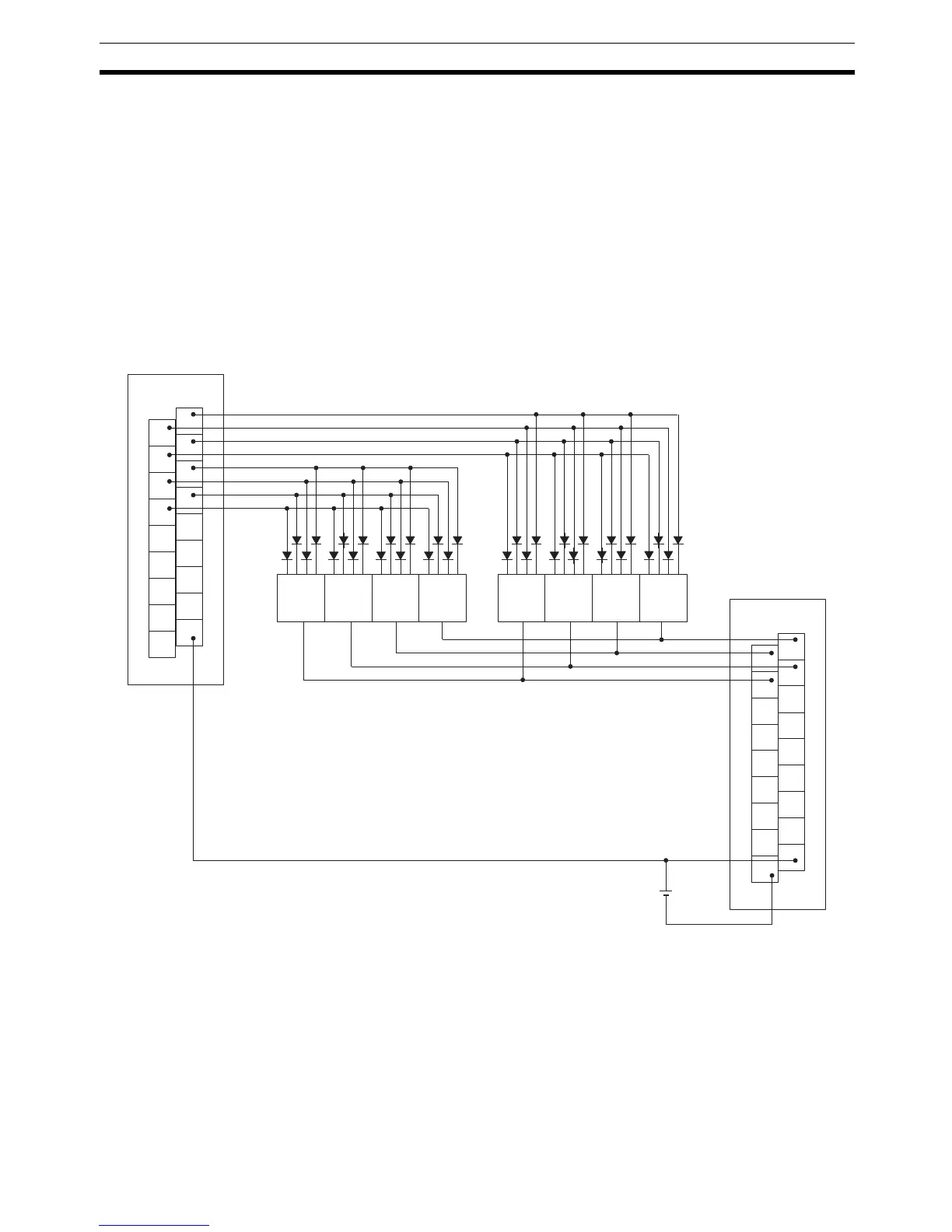
External Connections Connect the digital switch or thumbwheel switch to Input Unit contacts 0 to 7
and Output Unit contacts 0 to 4, as shown in the following diagram. The fol-
lowing example illustrates connections for an A7B Thumbwheel Switch.
The inputs and outputs can be connected to the following kinds of Basic I/O
Units and High-density I/O Units as long as they are not mounted in a SYS-
MAC BUS Remote I/O Rack.
• DC Input Units with 8 or more input points
• Transistor Output Units with 8 or more output points
1
3
5
7
9
11
13
15
COM
0
2
4
6
8
10
12
14
COM
ID212
1
3
5
7
9
11
13
15
COM
0
2
4
6
8
10
12
14
DC
OD212
1248
76 5 4 3 2 1C
Input Unit
Switch no. 8
Output Unit
Note The data read signal is not connected in this example.
A7B
Thumbwheel
Switch