944
Basic I/O Unit Instructions Section 3-23
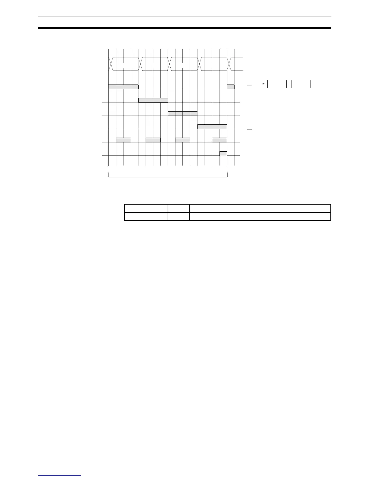
Timing Chart
Flags
Precautions Do not read or write the system word (C2) from any other instruction.
DSW(210) will not operate correctly if the system word is accessed by another
instruction. The system word is not initialized by DSW(210) in the first cycle
when program execution starts. If DSW(210) is being used from the first cycle,
clear the system word from the program.
DSW(210) will not operate correctly if I/O refreshing is not performed with the
Input Unit and Output Unit connected to the digital switch or thumbwheel
switch after DSW(210) is executed. Consequently, set the input time constant
for the Input Units used for the data line input word to a value that is shorter
than the cycle time, or do not connect the digital switch or thumbwheel switch
to the following Units.
• Basic I/O Units or High-density I/O Units mounted in a SYSMAC BUS
Remote I/O Slave Rack
• Communications Slaves (DeviceNet or CompoBus/S Slaves)
Example In this example, DSW(210) is used to read an 8-digit number from a digital
switch and outputs the resulting value constantly to D00000 and D00001. The
digital switch is connected through CIO 0100 (allocated to a CS1W-ID211 16-
point DC Input Unit) and CIO 0200 (allocated to a CS1W-OD211 16-point
Transistor Output Unit).
00
01
02
03
04
05
O
10
0
10
1
10
2
10
3
D+1 D
0 1 2 3 4 5 6 7 8 9 10 11 12 13 14 15 16
I
Leftmost
4 digits
Rightmost
4 digits
Input data
CS signals
One Round Flag
RD (read) signal
16 cycles to complete one round of execution
Eight digits: 00 to 03, 04 to 07
Four digits: 00 to 03
When only 4 digits are read,
only word D is used.
Name Label Operation
Error Flag ER OFF