EasyManuals Logo

Parker Compax3 User Manual

Parker Compax3
398 pages
To Next Page IconTo Next Page
To Previous Page IconTo Previous Page
Page #134 background imageLoading...
Page #134 background image
Setting up Compax3
C3I12T11
132
192-120113 N08 C3I12T11 - December 2010
Signal “position reached” turns into “velocity reached”.
Signal “position reached” shows that the drive is at a standstill.
No position monitoring takes place in status START (M.E5=24VDC or
CW.13=1)
Therefore reset the start signal to 0 after the START edge.
After Power On O1 (=SW Bit 9) = “0”
After the machine zero run (after position 0 is reached) O1 and SW.9 goes to “1”
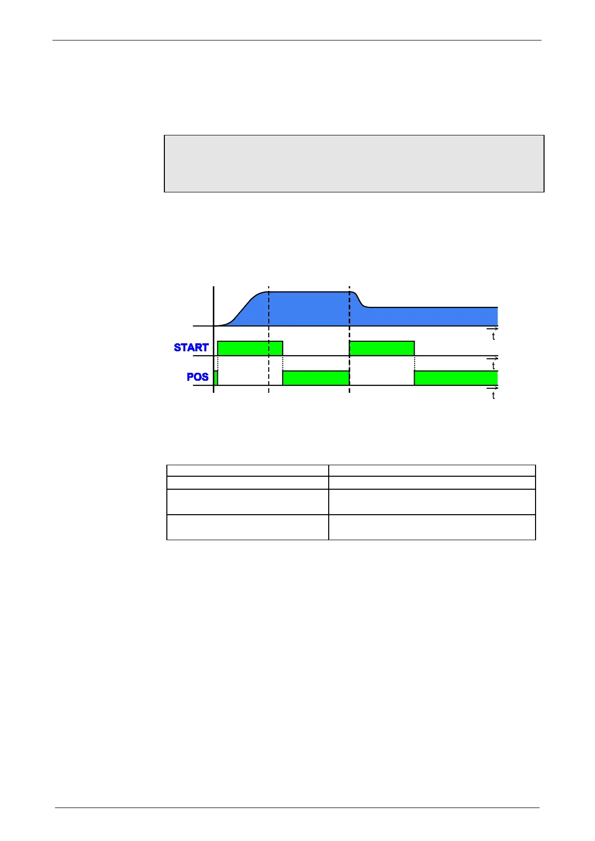
Example:
START: M.E5 or CW.13 = "1"
POS: O1: Position reached (= CW Bit 9)
Sequence:
PLC
Reaction Compax3
START of a positioning Position reached goes to "0"
From position reached = "0" follows:
START = 0
Positioning completed Position reached = "1"
From position reached = "1" follows:
Next START can take place
Position reached goes to "0"
Velocity
STOP
Behavior of
"Position reached"
after Power On
Handshake with PLC
for small
positionings

Table of Contents

Other manuals for Parker Compax3

Questions and Answers:

Question and Answer IconNeed help?

Do you have a question about the Parker Compax3 and is the answer not in the manual?

Parker Compax3 Specifications

General IconGeneral
Protection ClassIP20
Control ModesTorque, Speed, Position
Feedback OptionsIncremental encoder, Absolute encoder, Resolver
Communication InterfacesCANopen, EtherCAT, Profinet
Safety FeaturesSTO (Safe Torque Off), SS1 (Safe Stop 1), SOS (Safe Operating Stop)
Input Voltage200-480 VAC
Relative Humidity5% to 85% (non-condensing)
Shock ResistanceAccording to EN 60068-2-27
Operating Temperature0°C to +40°C

Related product manuals