Parker EME
Setting up Compax3
192-120113 N08 C3I12T11 - December 2010
Changing objects O100.1 and O100.2 may cause the control to be deactivated!
Protect dangerous areas!
External command value
During external setpoint specification, please respect the structure images for
electronic cams or gearboxes for signal filtering with external setpoint
specification (see on page 238) !
Complementary structure for load control (see on page 161).
Compax3 controller structures (see on page 206, see on page 212, see on page
214).
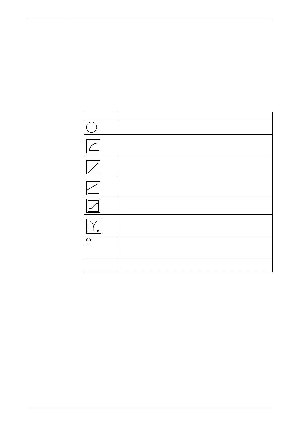
Symbol Description
p
Proportional term
signal is multiplied with K
p
First order delay component (P-T1 term)
Integration block (I-block)
PI-block
Limitation block (signal limitation)
Notch filter (band elimination filter)
Addition block
blue
description
Optimization objects
(simple pointer line)
red
description
Status objects
(pointer line with vertical stroke)