Parker EME
Compax3 device description
192-120113 N08 C3I12T11 - December 2010
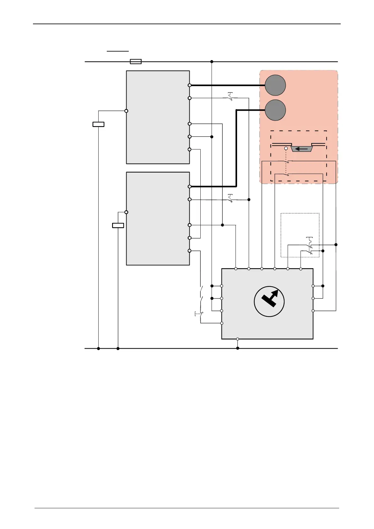
Circuit:
GND24V
A2
A1
S3
S2
K2
K2
K1
K1
EN
S1
I4 I3 I2 I1
X1
X2
S2
Q3
Q4
+24V
S6
S6
motor
motor
Safety door closed
Schutztür geschlossen
Danger Zone
Gefahrenbereich
S5
Not-Stop
Emergency
switch off
UE410-MU
Delay
Time
S4
FUNCTION
0
1
2
3
4
5
6
7
8
9
X4.5
X4.4
X4.3
X12.4
Energize *
Feedback
Feedback
Enable
Controller
Feedback
Compax3S
X3
X4.5
X4.4
X4.3
X12.4
Energize *
Feedback
Feedback
Enable
Controller
Feedback
Compax3S
X3
Energize / Ackn = I0 (X12/6)
Instead of the safety switching device manufactured by Sick mentioned above, you
may use other safety switching devices.
The safety switching device must however provide the following features:
1 normally open contact is required for switching off channel 1
(as an alternative, a safe semiconductor output is possible)
1 off-delayed normally open safety contact is required for switching off channel 2
(as an alternative, a safe semiconductor output with adjustable delay time for the
high_to_low_edge is possible).
1 one-channel monitoring circuit where the feedback contacts of channels 1 and
2 can be integrated for simultaneous monitoring, is required.
At the same time it must be possible to integrate a one-channel start button for
activation of the safety switching device into the circuit.
A new start may only be successful, if it is ensured, that channels 1 and 2 are
switched off.
1 two-channel connection for emergency power off and/or safety door contacts
with cross fault monitoring is required.
The safety switching device must feature performance PL e. The I/Os must at
least correspond to category 3.