Do you have a question about the Prevac MG15 and is the answer not in the manual?
Details on MG15 device versions and software changes available on the DOWNLOAD tab.
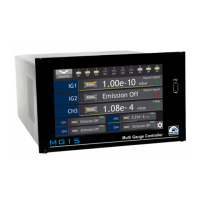
Explains the purpose and capabilities of the MG15 multi gauge controller in process control systems.
Comprehensive safety requirements for operating and handling the MG15 device.
Provides mechanical data and dimensions for the MG15 device.
Detailed technical specifications including electrical, measurement, communication, and mechanical parameters.
Procedure for unpacking the MG15, inspecting for damage, and retaining packaging.
Guidelines for mounting the MG15 in a cabinet or rack, adhering to safety notes.
Details on the device's cooling system, air flow requirements, and operating temperature limits.
Instructions for connecting the MG15 to the mains power supply, including grounding.
Description of sockets and connections available on the rear panel of the MG15.
Steps to power on the MG15 device correctly and readiness for operation.
Identifies key elements of the MG15's front panel, including display and ports.
Description of the front panel components for the MG15 BlackBox version.
Overview of the MG15's touch screen interface, including main, chart, and timer windows.
Explanation of the main window elements, displaying vacuum channel parameters.
Details on using the chart module to visualize physical quantities over time.
Description of the timer window for timing operations and setting time values.
Guide to using the numeric keypad for entering and editing numerical values.
Explanation of the on-screen alphanumeric keyboard for text input.
Accessing and configuring device parameters through the setup menu.
How to create and utilize shortcuts for frequently used settings and commands.
Understanding and interpreting warning and error messages displayed by the MG15.
Instructions for playing video files stored on the device.
Accessing various device setup options like chamber geometry and communication settings.
Detailed breakdown of the device's menu structure for parameter configuration.
Essential steps for the initial configuration and start-up of the MG15 device.
Procedure for configuring communication interfaces, such as RS232, for the MG15.
Instructions on how to change the device's operating language.
Describes status and error notifications displayed in the pressure value/information box.
Details on errors and warnings appearing in the message bar on the screen.
Information on notifications presented after user interaction, including copy errors.
Overview of communication protocols (Modbus RTU/TCP, ProfiNet) and standards for the MG15.
Recommendations for selecting appropriate cables for serial communication systems.
Description of available communication interfaces like RS232/RS485, Ethernet, and ProfiNet.
Details on Modbus RTU and TCP protocols for data exchange and device control.
Notes on the MG15 requiring no special maintenance work.
Instructions for cleaning the exterior of the MG15 with a moistened cloth.
Steps for updating the MG15's software/firmware via USB memory stick.
How to access and use the Preboot Environment for device startup and tool execution.
Recommendation to retain original packaging for storage and shipping.
Conditions for storing the MG15, including ambient temperature and humidity.
Guidelines for the proper disposal of the MG15 according to WEEE regulations.
Table detailing DIP switch settings for device addressing.
| Category | Controller |
|---|---|
| Input Voltage | 24 VDC |
| Number of Inputs | 8 |
| Communication Interface | RS485 |
| Operating Temperature | 0 - 50 °C |