COMMUNICATION MULTI GAUGE CONTROLLER
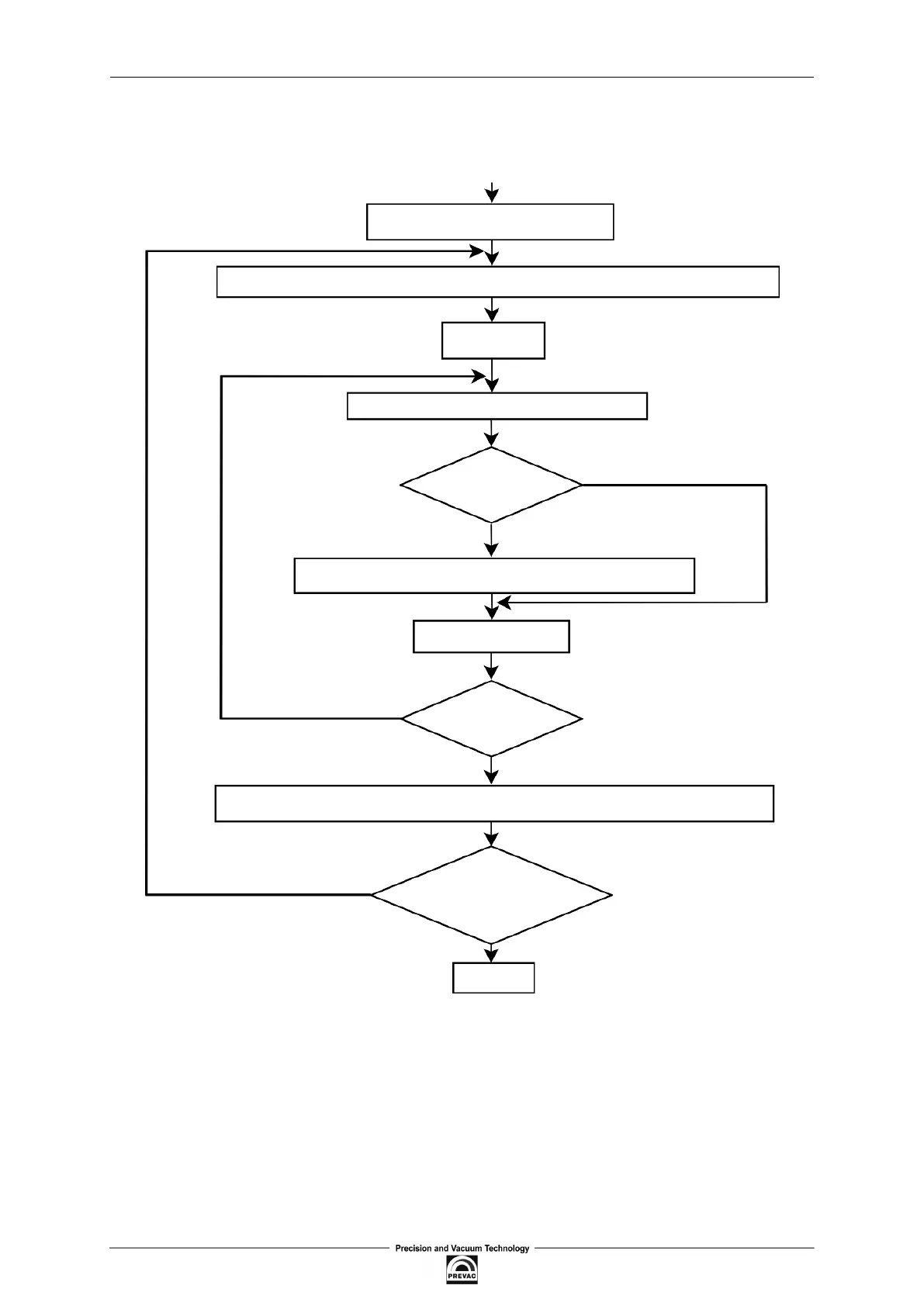
Figure 6.7 illustrates this algorithm of checking CRC errors.
Symbol ’⊕’ indicates XOR operation. “n” means a number of data bits.
START
0xFFFF →CRC Register
CRC Register ⊕ next byte of the message →CRC Register
0 →n
Shift CRC Register right one bit
Overlow?
NO
YES
CRC Register ⊕ 0xA001 →CRC Register
n + 1 →n
n > 7?
NO
YES
CRC Register ⊕ A001h →CRC Register
Is message complete?
NO
YES
END
Figure 6.7: Checksum calculation algorithm
Page 92 User manual rev. 03