COMMUNICATION MULTI GAUGE CONTROLLER
continued from previous page
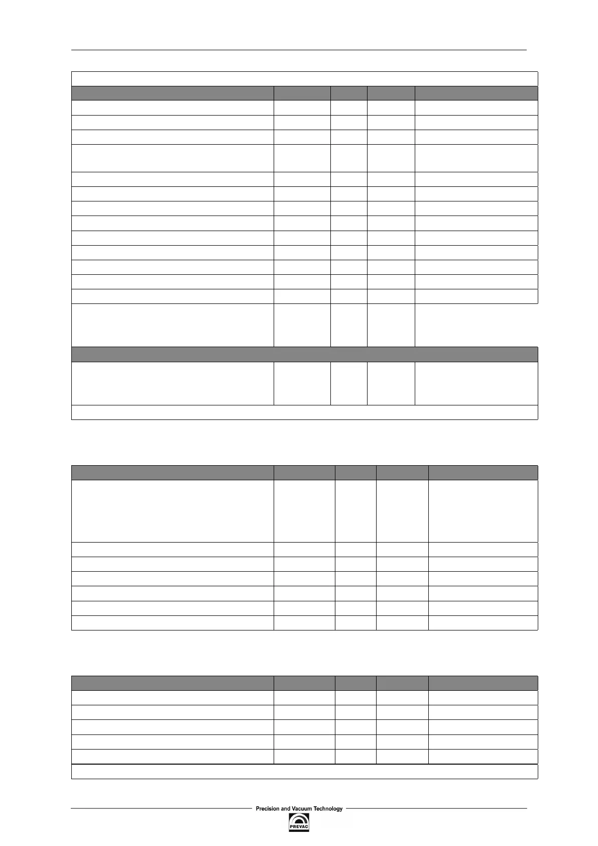
NAME OF VARIABLE ADDRESS TYPE KIND RANGE [UNIT]
Channel 7 - Auto identiication 185 R/W UINT8 0 .. 1
Channel 7 - Gauge type 186 R/W UINT8 see tab. 6.17
Channel 7 - Emission control 187 R/W UINT8 see tab. 6.19
Channel 7 - ilter: 0 - Low
1 - Medium
2 - High
188 R/W UINT8 0 .. 2
Channel 7 - Gas type 189 R/W UINT8 see tab. 6.20
Channel 7 - def. correction factor 190 R/W UINT16 0 .. 999
Channel 7 - Degassing time 191 R/W UINT8 0 .. 20 [min]
Channel 7 - current time to complete degassing (min) 192 R UINT8 0 .. 20 [min]
Channel 7 - current time to complete degassing (sec) 193 R UINT8 0 .. 59[sec]
Channel 7 - Factor A of def. gauge 194 R/W INT16 -30000 .. 30000
Channel 7 - Factor B of def. gauge 195 R/W INT16 -30000 .. 30000
Channel 7 - Min. voltage of def. gauge 196 R/W UINT16 0 .. 10000
Channel 7 - Max. voltage of def. gauge 197 R/W UINT16 0 .. 10000
Channel 7 - Full scale param. of def. gauge 198 FLOAT 0.00001
..
40000.00000
[Torr]
ADDITIONAL VACUUM SETTINGS
Flux Monitor ON/OFF:
bit0: Flux Monitor for channel 1
bit1: Flux Monitor for channel 2
bit2: Flux Monitor for channel 3
200 R/W UINT8 bits ield
(*) - the unit depends on the Flux Monitor ON/OFF option
Table 6.12: Basic registers table
NAME OF VARIABLE ADDRESS TYPE KIND RANGE [UNIT]
Remote control enable
Write:
0 - do nothing
1 - release remote control
Read: actual status of remote enable
1100 R UINT8 0 .. 1
Logical group 1101 R/W UINT8 0 .. 255
DHCP 1102 R/W UINT8 0 .. 1
IP address 1103 R/W 4*UINT8
Subnet mask 1105 R/W 4*UINT8
Default gate address 1107 R/W 4*UINT8
Port 1109 R/W UINT16 502,1025 .. 65535
Table 6.13: Communication registers map
NAME OF VARIABLE ADDRESS TYPE KIND RANGE [UNIT]
Digital output 1 - assigned signal 1300 R/W UINT8 see tab. 6.22
Digital output 1 - status 1301 R UINT8 0 .. 1
Digital output 2 - assigned signal 1302 R/W UINT8 see tab. 6.22
Digital output 2 - status 1303 R UINT8 0 .. 1
Digital output 3 - assigned signal 1304 R/W UINT8 see tab. 6.22
continued on next page
Page 104 User manual rev. 03