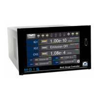
COMMUNICATION MULTI GAUGE CONTROLLER
It is recommended to make all the settings of the communication interface
before connecting to the Ethernet network. It is not necessary, however, the
MG15 default settings may cause conlicts with the devices already connected
to the network.
In case of the Modbus TCP network there are several other parameters: IP
address, subnet mask, network default gate address and DHCP. Changing any
of these parameters may assign immediately a new network address to the
device. Therefore, it is recommended to make such changes when the device is
in the “ofline” mode, i.e. disconnected from the communication network.
Each MG15 device has its own unique MAC address, usually as a 12-digit hexadecimal number in
the ”aa-bb-cc-dd-ee-ff” format. The MAC address can be viewed in the device menu or through the
communication interface according to the data in the table of chapter ??.
6.4.4.3 FRAME FORMAT
Typical data exchange consists in sending a query from the MASTER device and a response to this
query from the SLAVE device.
A typical message in both directions should consist of the following information:
Transaction Id Protocol Id Data length Device address Function code Data
2 bytes 2 bytes 2 bytes 1 byte 1 byte n bytes
Table 6.7: Modbus TCP frame format
• Transaction ID - used to synchronise messages between the server and client.
• Protocol ID - identiier of data exchange protocol, which is always 0 for Modbus TCP.
• Data length - number of bytes in a frame excluding transaction Id and protocol Id.
• Device address - device address to which a frame is directed or response to an address.
• Function code - 1-byte code unequivocally identifying action to be executed by the Slave
device.
• Data - length and type of data depends on the function code. Usually, a data segment will
contain the parameter address and number of data to read or write.
DEVICE IDENTIFICATION IN MODBUS TCP NETWORK
The Modbus TCP speciication enables also addressing the device as a part of
the Modbus protocol frame (“Device address” byte). In the Ethernet network
is it however oversized (the address is set to 0x01), and the main and fully
suficient device identiication is executed through the IP address of the device
in the network.
Page 94 User manual rev. 03