COMMUNICATION MULTI GAUGE CONTROLLER
6.3.3 PROFINET CONNECTOR (OPTION)
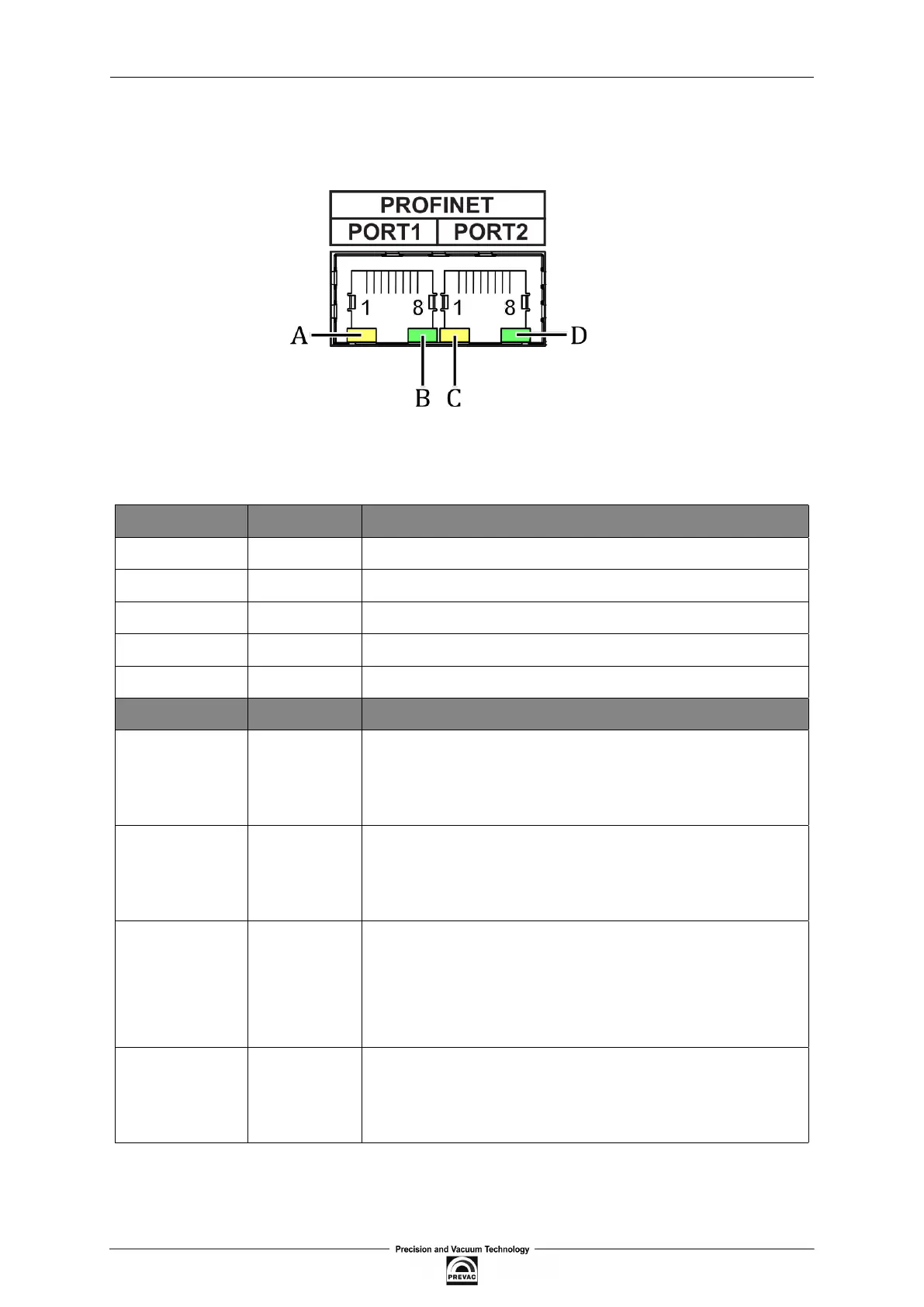
Figure 6.5: Female socket of ProiNet (Modbus RTU) interface
PIN NUMBER FUNCTION DESCRIPTION
1 TX+ Data transmission - differential pair positive conductor
2 TX- Data transmission - differential pair negative conductor
3 Rx+ Data reception - differential pair positive conductor
6 Rx- Data reception - differential pair negative conductor
4,5,7,8 N/C Not connected
DIODE FUNCTION DESCRIPTION
A Error disabled - no connection, activity
(yellow) status always on - device error
blinking - module test identiication
B Connection disabled - no connection, activity
(green) status always on - connection in the network, no trafic
for Port 1 blinking - connection active, trafic in the network
C Connection disabled - no voltage or IP address
(yellow) status always on - network active, connection
blinking 10Hz - device error
blinking 2 Hz - waiting for connection/coniguration mode
D Connection disabled - no connection, activity
(green) status always on - connection in the network, no trafic
for Port 2 blinking - connection active, trafic in the network
Table 6.3: Pins description of ”PROFINET” connector
Page 86 User manual rev. 03