MULTI GAUGE CONTROLLER COMMUNICATION
6.4.3 MODBUS RTU
The serial communication for the Modbus RTU is make through EIA232, EIA485 (formerly RS232
and RS485) or optionally ProiNet (as encapsulation of the data frame) transmission. The EIA stan-
dards have been introduced by the Electronics Industry Association and describe the electrical
characteristics of communication networks. Table 6.4 includes the summary of different physical
layers described by these two standards.
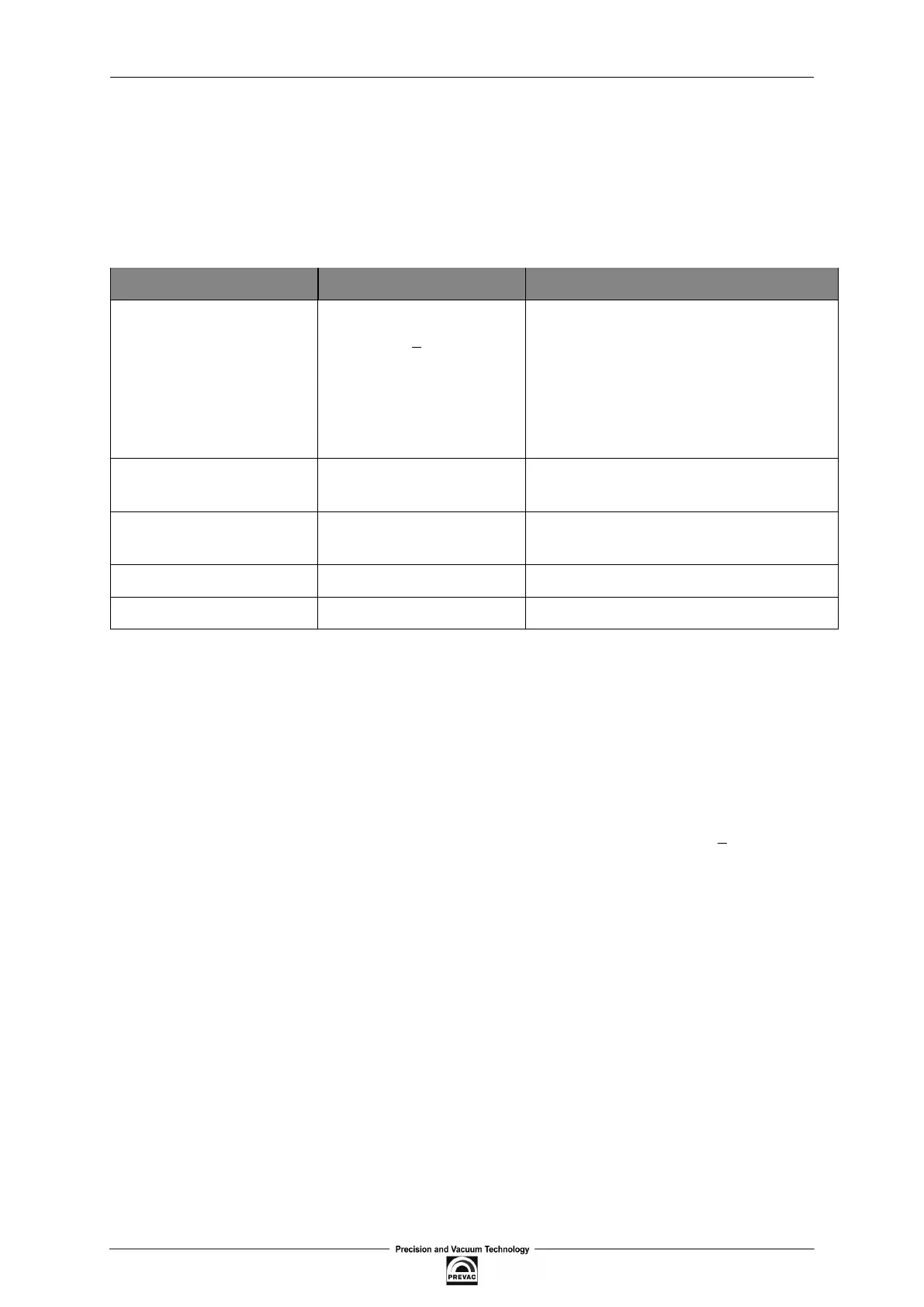
EIA Standard EIA232C EIA485 3-wire
Transmission type From point to point,
nominally +12Volt (min
3V, max 15V)
One or Two Pairs of wires. Differential
Mode. Half duplex - communication oc-
curs in both directions but not at the
same time. Typically once a unit be-
gins receiving a signal it must wait for
the transmitter to stop sending before
it can reply.
Electrical connections 3 wires: Tx, Rx,
GND(common)
3 wires: A, B, C(common)
Number of devices in the
line
1 transmitter, 1 receiver 31 receivers, 1 transmitter
Maximum data rate 115,2Kb/s 10Mb/s
Maximum cable length 15m 1200m
Table 6.4: EIA Standard
Note 1: The EIA232C standard enables connecting one device to a computer, PLC controllers or
similar devices with a cable max. 15m long.
Note 2: The EIA485 standard enables connecting at least one device to a computer, with a cable
max.
1200m
long. In this way up to 31 receivers (SLAVE) and one transmitter (MASTER) can be
connected. EIA485 is a balanced two-conductor transmission system, which means that informa-
tion is carried out by the difference in voltage between two conductors, instead of the voltage in
relation to the common conductor or ground, as it is done in EIA232C. One voltage polarity indi-
cates logic “1”, reverse polarity indicates logic “0”. The difference must be at least +200mV. The
EIA485 differential transmission is less vulnerable to inluence of external signals and if the de-
vice is in an environment with substantial interference, it should be used instead of the EIA232C.
Even though the EIA485 standard is commonly described as a two-conductor connection, a chassis
ground/screen two-conductor connection as a “common” signal should be used to ensure addi-
tional protection against interference.
Note 3: The MG15 works in a half-duplex system, which does not enable transmission and reception
of data in the same time. Data are transmitted interchangeably, once query, once response.
Note 4: Most PC computers is equipped with an EIA232 port for communication. A limit of 32
devices may be bypassed by dividing most networks into segments, which are electrically isolated.
When communication with more than 32 devices on the same bus is require, a PC computer with a
special EIA485 attachment is required for buffering EIA485 networks. It can also be used to change
a 3-conductor EIA485 to a 5-conductor EIA485.
Note 5: For EIA485 connection between the MG15 devices and a MASTER device, in particular
at greater distances and transmission speeds (>38400bps, >10m) it is recommended to use a 2-
conductor twisted pair, preferably, with an additional screen. Remember also to add a terminator
(120Ω...470Ω resistor connected between lines A and B) at the beginning and the end of the EIA485
bus.
User manual rev. 03 Page 89