INSTALLATION MULTI GAUGE CONTROLLER
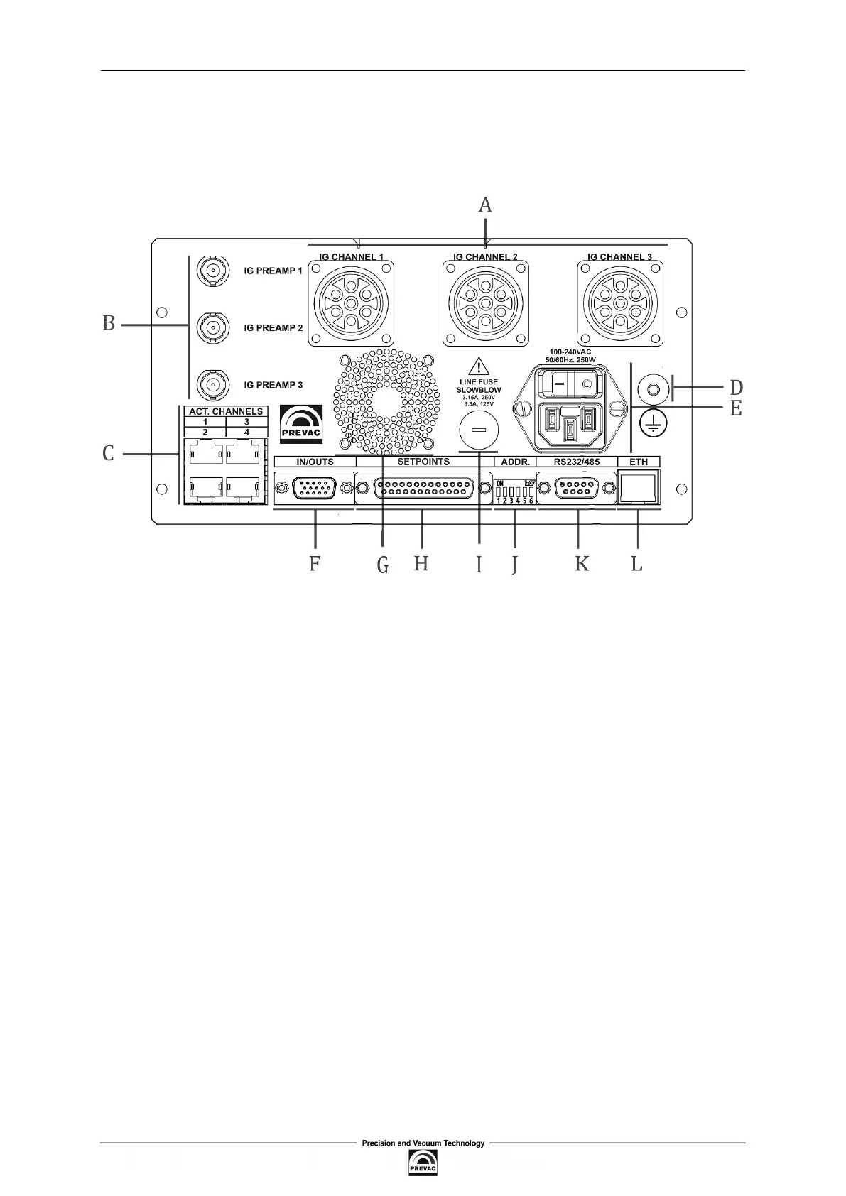
2.5 DEVICE REAR PANEL
This section describes the sockets and connections of the rear panel. Read this section to properly
connect the accessories available for the device.
Figure 2.2: View of the rear panel of the standard MG15 .
The following connections are installed on the rear panel:
• A - Passive gauges connections
• B - Connections for passive gauges measuring signal
• C - Active gauges connections
• D - Ground terminal
• E - Mains connection
• F - I/O interface
• G - Air outlet
• H - Connection for relay outputs
• I - Fuse socket
• J - Address DIP switch
• K - RS232/485 communication interface
• L - Ethernet communication interface
Page 22 User manual rev. 03