MULTI GAUGE CONTROLLER INSTALLATION
2.5.2 PASSIVE CHANNELS
The passive channels connections are used to connect passive gauges with hot cathode.
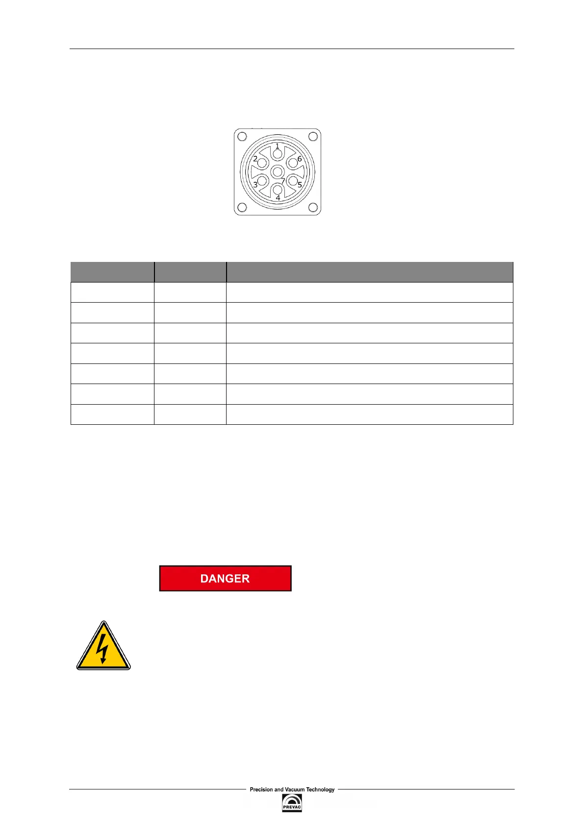
7-pin UTG (Metalok Bantam) sockets are available for the passive channels.
Figure 2.5: Passive channel socket (UTG-type)
PIN NUMBER FUNCTION DESCRIPTION
1 Filament Filament 1 supply (max. 6.5V 6A)
2 Filament Common ground for ilaments
3 Anode Anode pin
4 Relector Relector (extractor) pin
5 Not used Pin not used
6 Filament Filament 2 supply (max. 6.5V 6A)
7 PE Ground
Table 2.2: Description of pins of passive channel socket
MEASURING SIGNALS
The measuring signals, i.e. the ion currents are transferred via a coaxial cable (IG PREAMP).
Pin arrangement:
• inner conductor - signal conductor
• outer conductor – shielding
Dangerous voltage.
As soon as the emission is switched on, both connections carry hazardous
levels of voltage.
The device must be switched off before any work related to connecting a gauge
is performed. After switching off, wait approx.15 seconds before starting the
work.
User manual rev. 03 Page 25