MULTI GAUGE CONTROLLER INSTALLATION
2.5.4 I/O INTERFACE
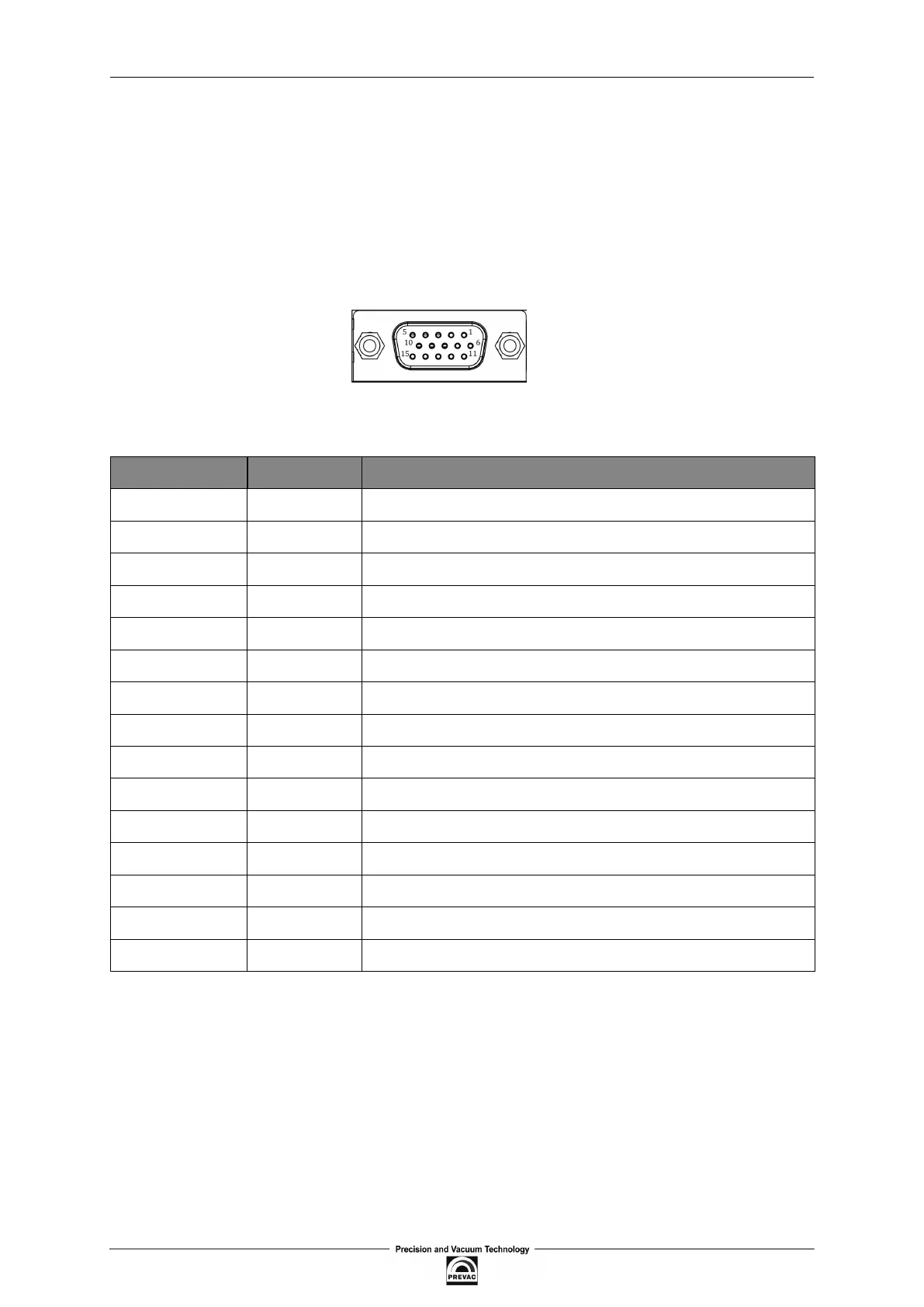
The I/O connections contains the following signal pins:
• digital inputs
• relay outputs
• analogue outputs
Figure 2.8: I/O socket (D-sub HD 15-pin female)
PIN NUMBER FUNCTION DESCRIPTION
1 DIN1 Digital input 1 (24 V voltage activated, type 5mA)
2 DIN2 Digital input 2 (24 V voltage activated, type 5mA)
3 DIN3 Digital input 3 (24 V voltage activated, type 5mA)
4 DIN4 Digital input 4 (24 V voltage activated, type 5mA)
5 GND Common ground for digital inputs 1..4
6 REL1_NO Relay output 1, contact normally open
7 REL2_NO Relay output 2, contact normally open
8 REL3_NO Relay output 3, contact normally open
9 REL4_NO Relay output 4, contact normally open
10 REL_COM Common pin for relay outputs 1..4
11 AOUT1 Analogue output 1 (0-10V)
12 AOUT2 Analogue output 2 (0-10V)
13 AOUT3 Analogue output 3 (0-10V)
14 AOUT4 Analogue output 4 (0-10V)
15 GND2 Common ground for analogue outputs 1..4
Table 2.3: Description of pins of I/O connection
User manual rev. 03 Page 27