COMMUNICATION MULTI GAUGE CONTROLLER
Note 6: The MG15 enables communication with a MASTER device with a write/read speed not
exceeding 100 frames/second.
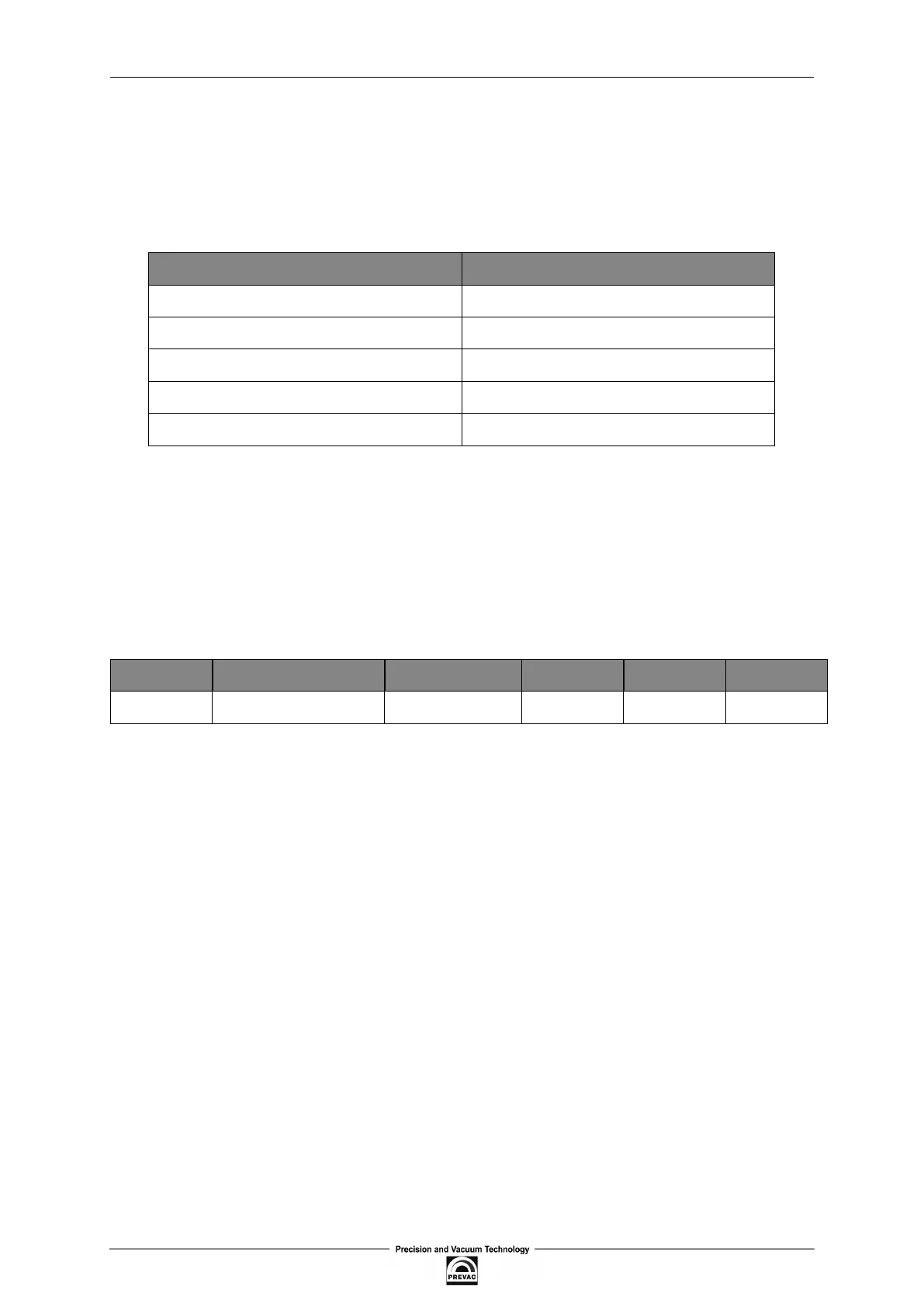
6.4.3.1 CONNECTION PARAMETERS
PARAMETER VALUE
Data bits 8
Parity None
Stop bits 1
Flow control None
Baudrate 57600 (default)
Table 6.5: Connection parameters
6.4.3.2 FRAME FORMAT
Typical data exchange consists in sending a query from the MASTER device and a response to this
query from the SLAVE device.
A typical message in both directions should consist of the following information:
Start Device address Function code Data CRC EOT
3 bytes 1 byte 1 byte n bytes 2 bytes 3 bytes
Table 6.6: Modbus RTU frame format
• Start - is an inactivity period, which equals to at least 3.5 times of the transmission time of a
single character. E.g. for baudrate 9600bps with 1 start bit, 1 stop bit and 8 bits of data, the
Start time is 3.5ms. Very often Start time results from the EOT time of the previous frame.
• Device address - unique 1-byte device address set on the jumpers in the rear panel (chapter
2.5.6). Address 0 is a broadcast address.
• Function code - 1-byte code unequivocally identifying action to be executed by the Slave
device.
• Data - length and type of data depends on the function code. Usually, a data segment will
contain the parameter address and number of data to read or write.
• CRC - 2-byte checksum used to check the correctness of data in a communication frame. Cal-
culation of checksum see chapter 6.4.3.3.
• EOT - the segment at the end of a frame showing to the slave devices that a new message
will be transmitted next. As a standard, at least 3.5 times of the transmission time of a single
character.
Page 90 User manual rev. 03