EasyManuals Logo

QUANTA Rackgo X Series F03A User Manual

Default Icon
162 pages
To Next Page IconTo Next Page
To Previous Page IconTo Previous Page
Page #142 background imageLoading...
Page #142 background image
CONNECTORS AND JUMPERS CONNECTORS AND JUMPERS
5-1
5.1 Connectors and Jumpers
Mainboard
Connectors
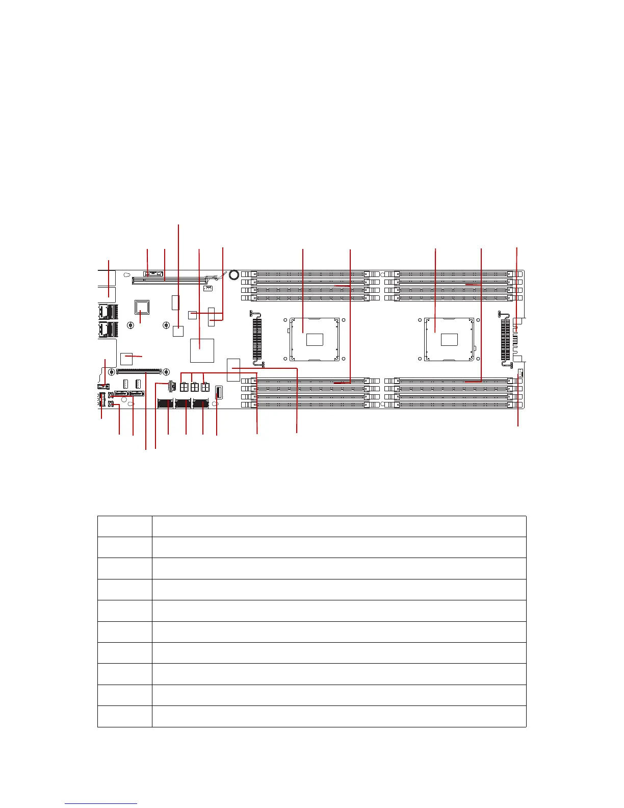
See the following figure and table for information on mainboard connectors.
Mainboard Connectors
\
Table 1: Mainboard Connectors
LOCATION DESCRIPTION
1 Processor (CPU1)
2 CPU1 DIMM connector (B0, B1, B2, B3, B4, B6, B7)
3 Processor (CPU0)
4 CPU0 DIMM connector (A0, A1, A2, A3, A4, A6, A7)
5 Power connector
6 Thermal sensors
7 External USB connector
8Super IO chip
9Debug connector
13
9
4
2
5
20
7
10
11
11
12
13
14
15
6
16
24
25
19
17
18
21
23
22
8
26

Table of Contents

Questions and Answers:

Question and Answer IconNeed help?

Do you have a question about the QUANTA Rackgo X Series F03A and is the answer not in the manual?

QUANTA Rackgo X Series F03A Specifications

General IconGeneral
BrandQUANTA
ModelRackgo X Series F03A
CategoryServer
LanguageEnglish

Related product manuals