CHIPSET SCREEN BIOS
3-21
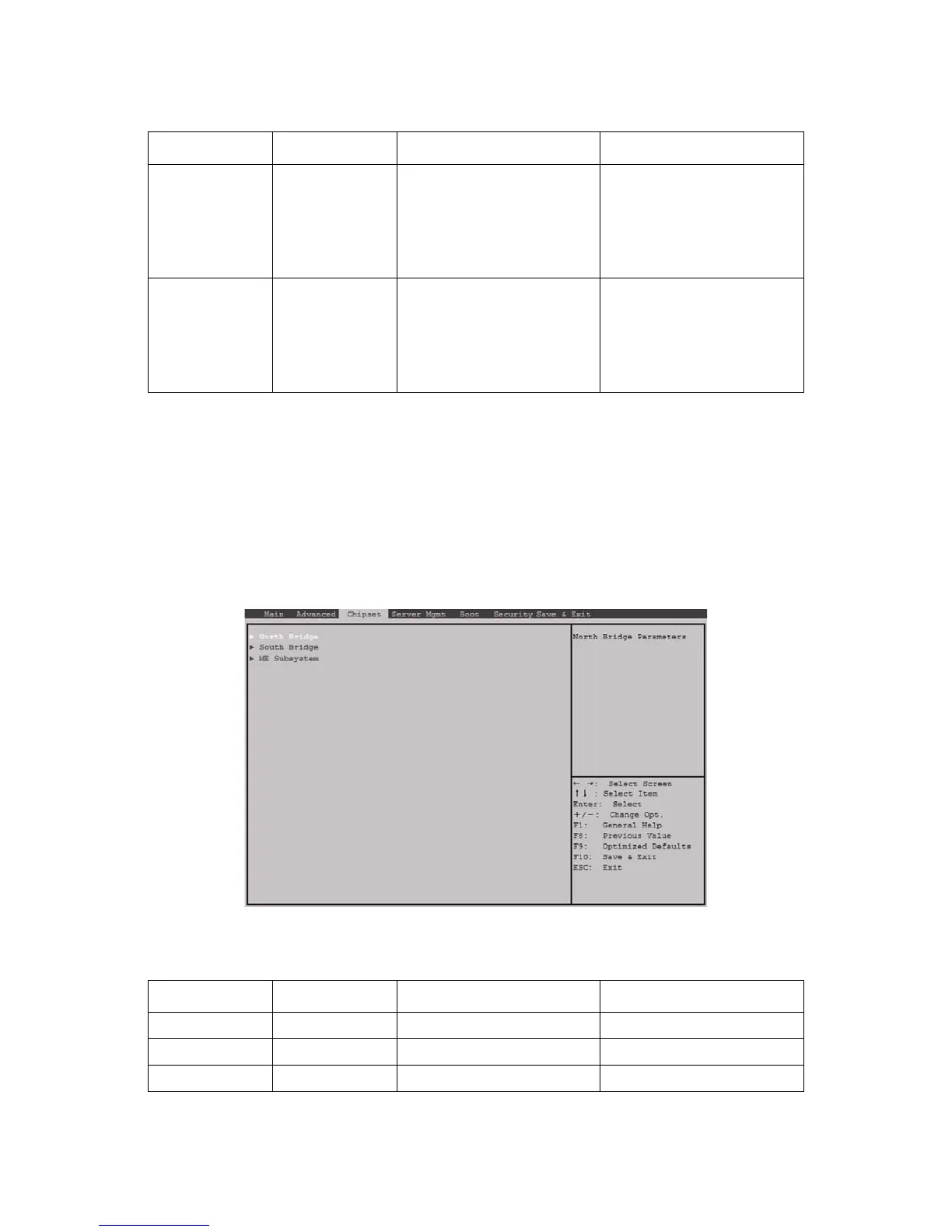
Chipset Screen
The Chipset screen provides an access point to configure several options. On this screen,
the user selects the option that is to be configured. Configurations are performed on the
selected screen, not directly on the Chipset screen.
To access this screen from the Main screen, press the right arrow until the Chipset screen is
chosen.
Figure 3-19. Chipset Screen
Stop Bits
[1]
[2]
Stop bits indicate the end of a
serial data packet. (A start bit
indicates the beginning). The
standard setting is 1. Commu-
nication with slow devices may
require more than 1 stop bit.
Flow Control
[None]
[Hardware RTS/
CTS]
It prevent data loss from buffer
overflow. Buffers are full: Send
‘stop’ signal; Buffers are empty:
Send ‘start’ signal. HW flow ctrl
uses two wires to send start/
stop signals.
Table 20: Chipset Screen Description
SETUP ITEM OPTIONS HELP TEXT COMMENTS
North Bridge North Bridge Parameters.
South Bridge South Bridge Parameters.
ME Subsystem ME Subsystem Parameters.
Table 19: Console Redirection Description (Continued)
SETUP ITEM OPTIONS HELP TEXT COMMENTS
 Loading...