ABOUT THE SYSTEM SYSTEM OVERVIEW
1-6
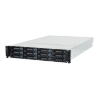
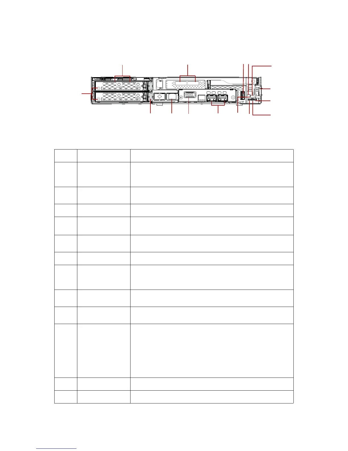
Node Front View
Figure 1-5. Node Front View
Table 5: Node Front View
NO.ITEM DESCRIPTION
1 HDD tray
Each HDD board can support up to 2 SAS/SATA HDDs
Tray is connected through an internal miniSAS and power cable to
Windmill MB SAS/SATA board
2
External mini-SAS
port
Supports up to 6 GB SAS connection (optional)
3 USB Standard USB 2.0 connector
4Power button
Press less than four seconds to activate power management event.
Press longer than four seconds to activate a hard power off.
5Reset button
Press to perform a hard reset and begin executing the BIOS initializa-
tion code.
6 Sled release latch Press and hold to release the system sled.
7
Power LED
(Blue)
Displays during power on state.
Blinking state indicates system ID event trigger. See Mainboard LEDs on
page 1-7.
8
HDD activity LED
(Green)
Displays during activity on the motherboard's SATA hard drive inter-
faces. See Mainboard LEDs on page 1-7.
9
Beep error LED
(Amber)
Provides PC speaker functionality by illuminating the LED in place of
the PC speaker audible tone. See Mainboard LEDs on page 1-7.
10 Debug header
14-pin (shrouded), right-angled, 2mm pitch connector; supports hot
plugging for existing debug cards.
Two 7-segment LED: displays firmware POST information and sys-
tem error codes.
One RS-232 serial connector: provides console redirection.
One reset switch: triggers system reset when pressed.
Designed with a notch for easy installation to avoid pin shifting.
11 NIC 10 Gb SFP + connectors (optional)
12 VGA Provides interface for an external display (optional)
 Loading...