INSTALLING HARDWARE DIMMS
2-16
2.6 DIMMS
This section includes the following information:
Memory population rules
DIMM installation procedures
Banks and Channels
The channels are designated a letter A for a single processor and B for dual processors
configuration.
Each bank is also identified by a designation, either 1 or 2. See the following illustration for
the bank and channel layout on the mainboard.
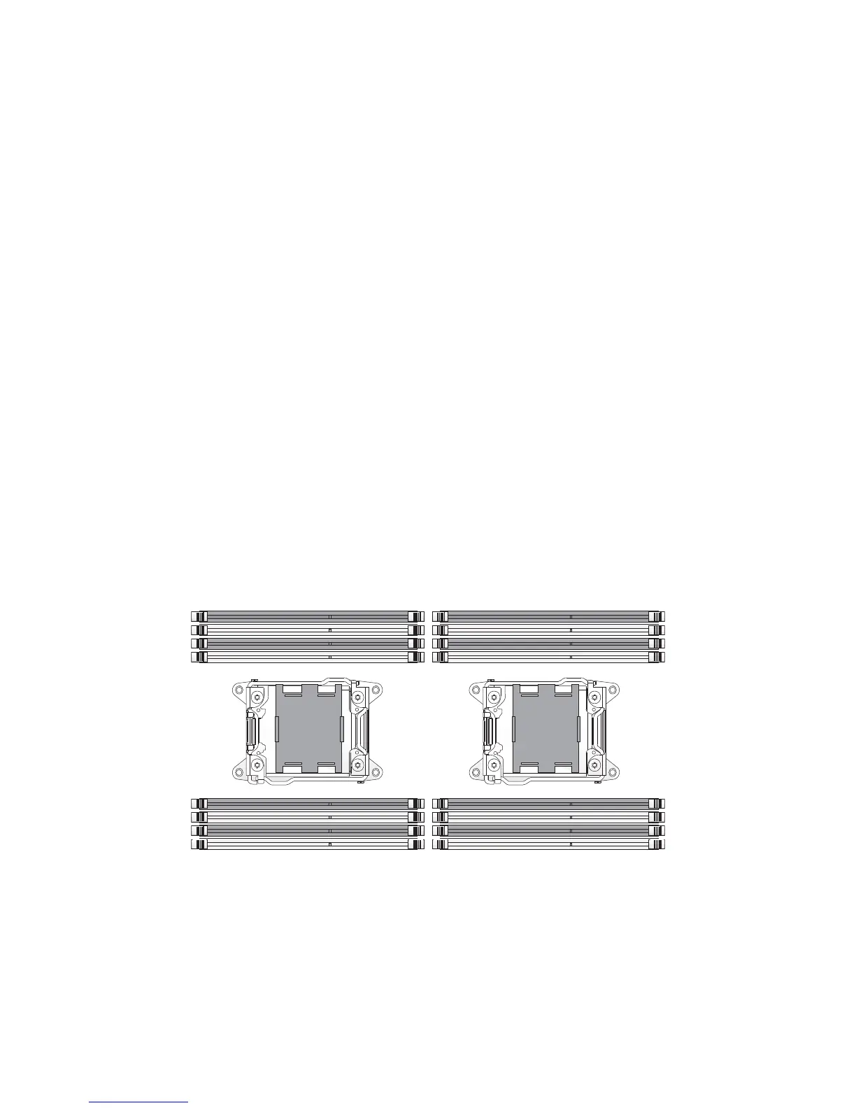
Figure 2-22. Bank and Channel Layout
Before installing or replacing memory modules, read the following information to become
familiar with memory performance guidelines and population rules. The information is pro-
vided as guidance for best server performance practices.
rz
Note that slots 0, 2, 4, and 6 within a bank are colored coded in white, while slots 1, 3, 5, and 7
are black.
A0, A1, A2, A3B0, B1, B2, B3
A4, A5, A6, A7B4, B5, B6, B7
Front SideRear Side
 Loading...