MIDPLANE CONNECTORS AND JUMPERS
5-3
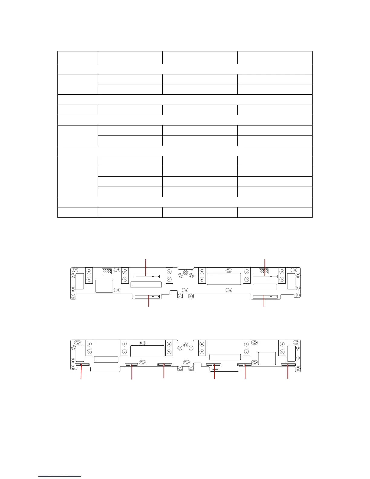
Midplane
Figure 5-1. Midplane Connectors (Front View)
Figure 5-2. Midplane Connectors (Rear View)
BIOS Recovery Jumper
J46
1-2 Normal Operation x
2-3 Recover BIOS
Manufacturing_DET Jumper
J48 1-2 Manufacturing_DET Open
ME Firmware Update Jumper
J49
1-2 Normal Operation x
2-3 ME in Force Update Mode
SLT#_CFG
J37
2-4 Normal 1x8 x
4-6 Slot 0 config as 2x4
1-3 Normal 1x8 x
3-5 Slot 1 config as 2x4
PCIE Slot JTAG/SMBus Select
J51 1-2 PCIE JTAG Open
Table 2: Mainboard Jumpers (Continued)
LOCATION JUMPER POSITIONS (PIN)FUNCTION DEFAULT SETTING
 Loading...