Instrument functions
R&S
®
LCX Series
104User Manual 1179.2260.02 ─ 02
For details on the trigger modes, see the data sheet, section "Digital trigger and control
interfaces".
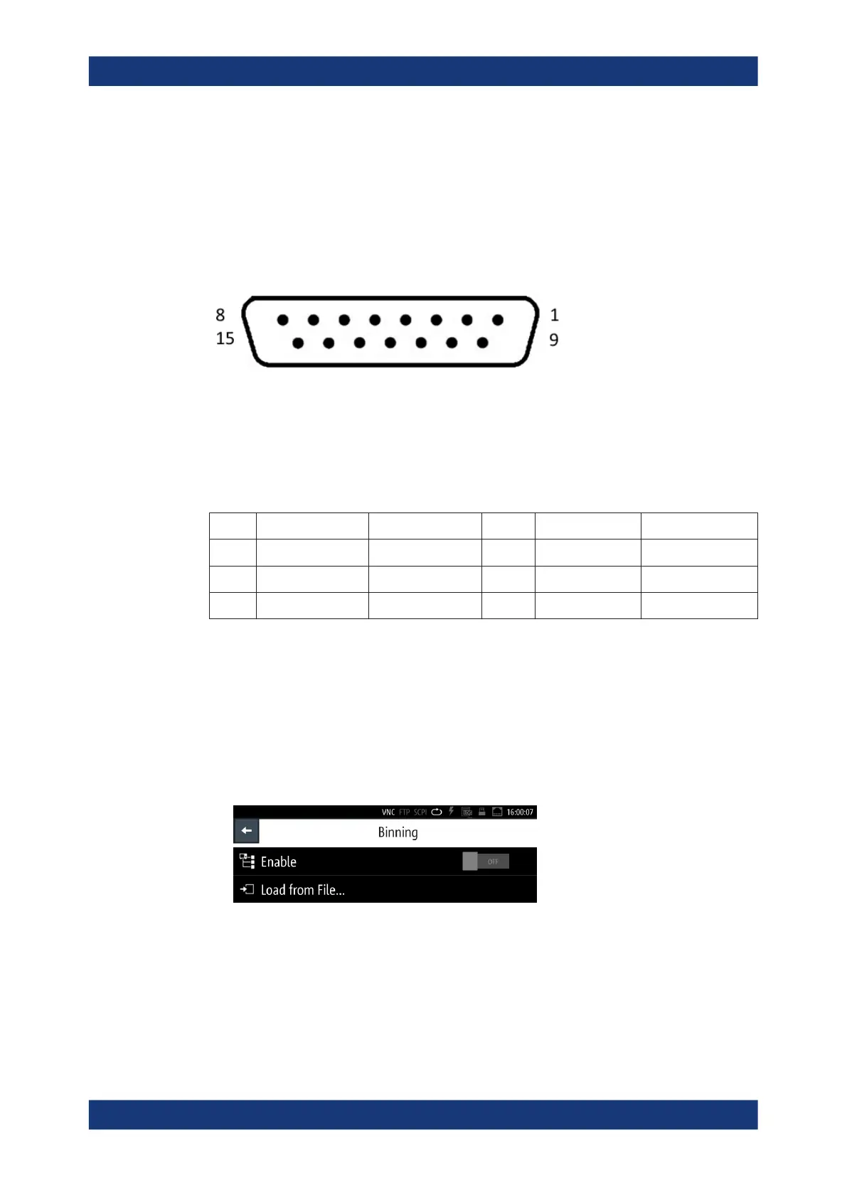
8.8.5.2 Assignment of the binning interface
The digital I/O port of the binning interface is a 15-pole D-Sub female socket, including
eight data lines. The remaining pins provide digital input and output of control signals.
Figure 8-22: Digital I/O connector, front view
See the data sheet, section "Digital trigger and control interfaces".
For details on the interface specification, see section "Digital trigger and control interfa-
ces" in the data sheet.
Table 8-1: Pin assignment
Pin Signal Direction Pin Signal Direction
1 - 8 Digital output 1 to 8 OUT 14 + 3.3 V OUT
9 - 10 Digital input IN 15 + 12 V OUT
11 - 13 GND OUT
8.8.5.3 Binning settings
In the "Binning" menu, you can upload the binning file, and start the measurement.
Access:
1. Press the [settings] key at the front panel.
2. In the "Functions" tab, select "Binning".
Figure 8-23: Binning menu
In the initial softkey menu, you can load the binning file and activate the measure-
ment.
During the process, the main screen indicates the parameters related to the mea-
surement, and access to the bin configuration.
Specific instrument functions

 Loading...


