Mixed Signal Operation (Option R&S RTC-B1)
R&S
®
RTC1000
108User Manual 1335.7352.02 ─ 02
●
"To label the individual bits of the logic probe" on page 109
To set the threshold for logic states
1. Press the POD key.
2. Press the MENU key in the Vertical section.
3. Set "SETUP" = "POD".
4. Press "THRESHOLD".
5. Set the threshold:
● Select the predefined level for "TTL", "CMOS" or "ECL".
● To set a user-defined level, select "User1" or "User2".
Adjust the logic level from –2 V to 8 V with the universal knob or the KEYPAD
key.
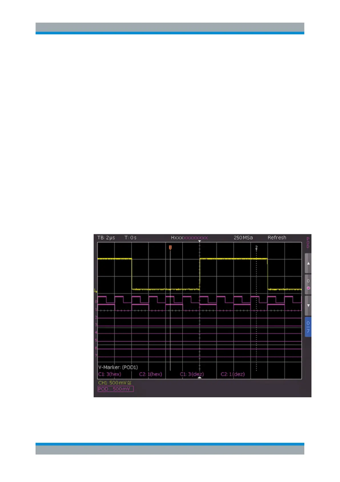
To activate and scale logic channels
1. To switch on the digital channels, press the POD key in the Vertical section.
The digital channels 0 to 7 are shown on the screen. A logic "1" is indicated by a
bar that is two pixels wide, and a logic "0" is indicated by a bar that is one pixel
wide. The logic threshold and a figure which shows the logical states are shown
next to the name "POD" in the information field in the bottom left of the display.
Figure 9-2: Logic channels: display settings
Using Logic Channels