Serial Bus Analysis
R&S
®
RTC1000
130User Manual 1335.7352.02 ─ 02
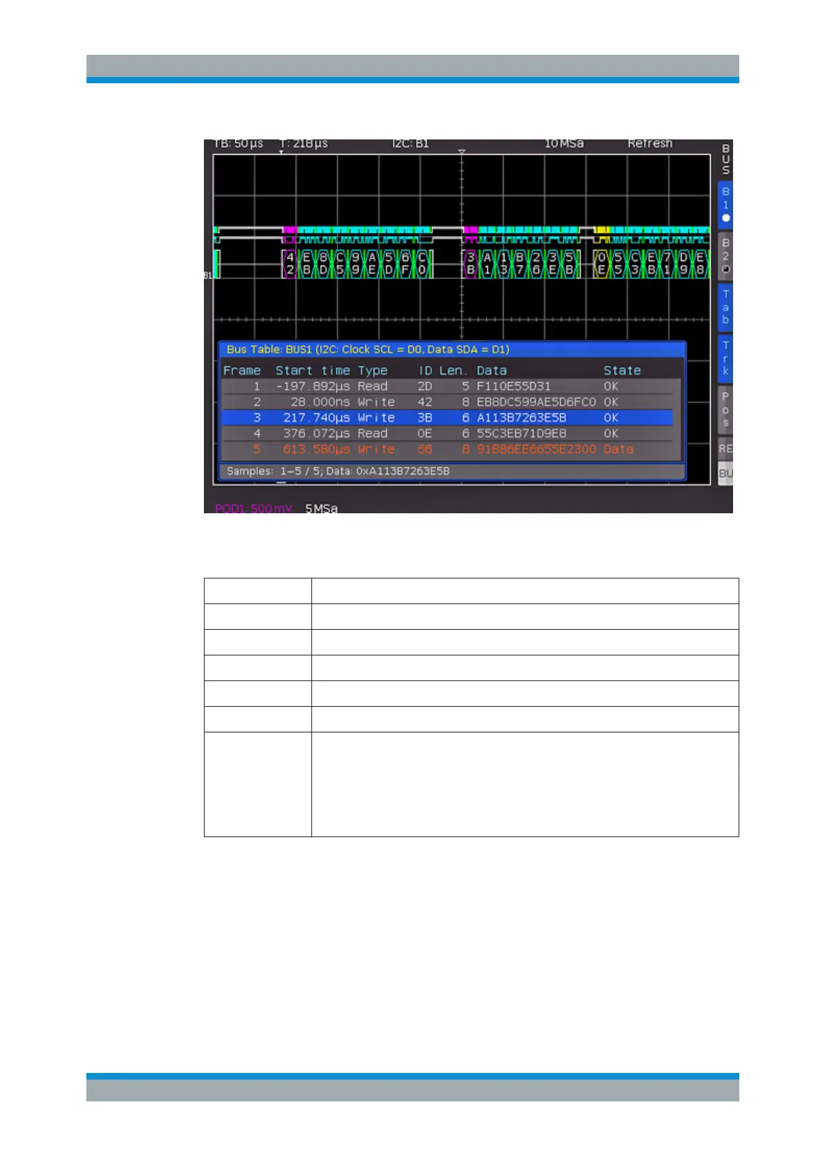
Figure 11-6: I2C bus table
Table 11-1: Content of the I
2
C bus table
Column Description
"Start Time" Time of frame start in relation to the trigger point
"Type" Value of the R/W bit (Read/Write)
"ID" Value of address
"Length" Number of words in the frame
"Data" Values of the data words
"State"
Frame state:
●
"OK" = frame is valid
●
"DATA" = during acquisition start/end only the frame start / frame end has been
decoded; currently no data available
●
"ADDR. ERR." = incomplete frame decoding
●
"INS" = the frame is not contained in the acquisition; the acquired part of the
frame is valid.
11.4 SPI / SSPI BUS (Option R&S RTC-K1)
For SPI/SSPI bus trigger and decoding, you need the R&S RTC-K1 option.
The Serial Peripheral Interface SPI is used to communicate with slow peripheral devi-
ces, in particular for the transfer of data streams. The SPI bus was developed by
Motorola; however, it has not been formally standardized. Generally, it is a bus with
clock and data lines and a select line (3-wire). If only one master and one slave are
SPI / SSPI BUS (Option R&S RTC-K1)