Getting Started
R&S
®
RTC1000
15User Manual 1335.7352.02 ─ 02
2.2 Instrument Tour
2.2.1 Front Panel
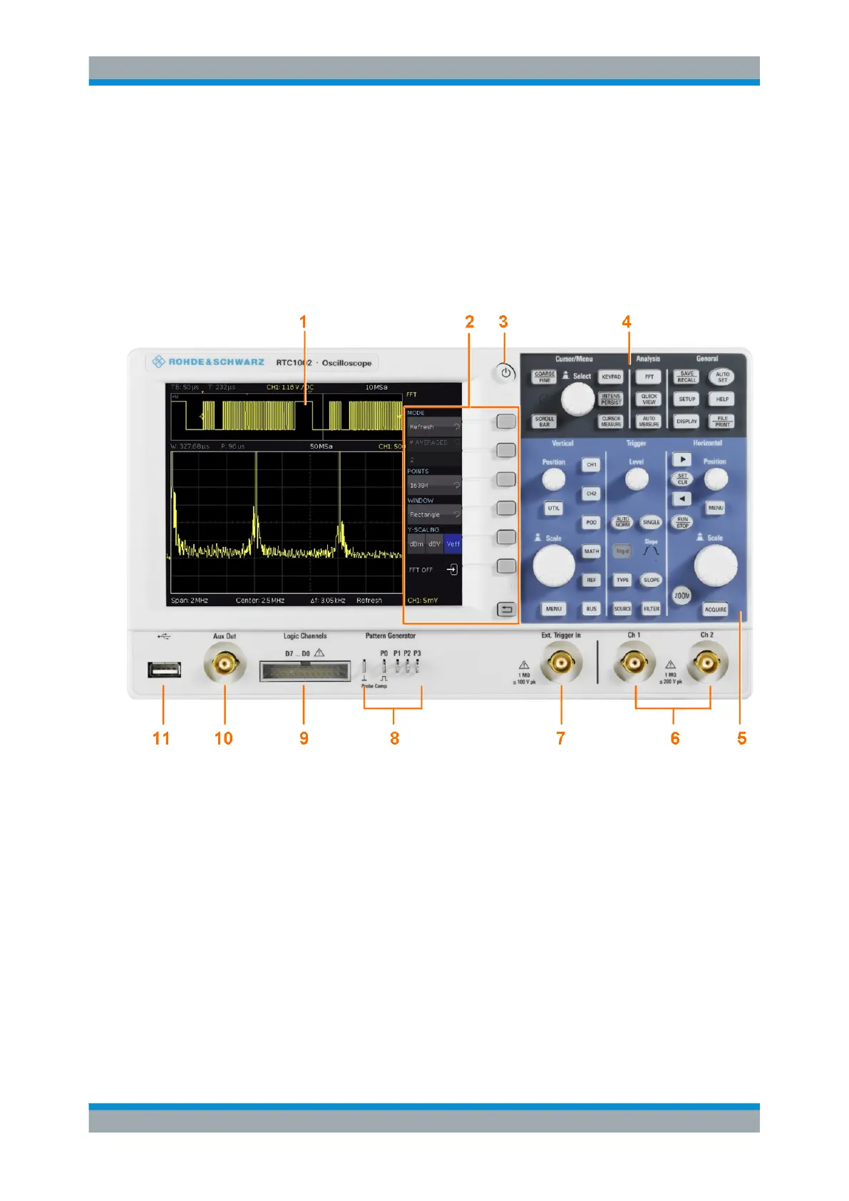
Figure 2-1 shows the front panel of the R&S RTC1000. The function keys are grouped
in functional blocks to the right of the display.
Figure 2-1: Front view of the R&S
RTC1000
1 = Touchscreen
2 = Softkeys and menu
3 = ON/OFF key
4 = Cursor/Menu, Analyze and General sections
5 = Vertical, Trigger and Horizontal sections
6 = BNC connectors of the analog channel inputs
7 = BNC connector of the external trigger input
8 = Pattern generator output (option R&S RTC-B6) and probe adjustment output
9 = Connector for the logic probe (option R&S RTC-B1)
10 = Multi-purpose BNC connector AUX OUT
11 = USB connector
Instrument Tour