Mixed Signal Operation (Option R&S RTC-B1)
R&S
®
RTC1000
112User Manual 1335.7352.02 ─ 02
To configure the parallel or parallel bus
1. In the "BUS" menu, press "CONFIGURATION".
2. Press "BUS WIDTH". Use the UNIVERSAL knob to select the number of bit lines.
3. Press "SOURCE".
4. Set the source lines of the individual bits:
a) Press "PREVIOUS BIT" or "NEXT BIT" repeatedly to select a bit. The selected
bit is highlighted in blue.
b) Turn the UNIVERSAL knob to assign a logic channel to the selected bit. Alter-
natively, you can press the "SOURCE" repeatedly.
5. If you have selected "PARALLEL CLOCKED" as bus type, press the bottom soft-
key "CONTROL WIRES" to set the following:
a) Press "CHIP SELECT" and select the CS source.
b) Press "ACTIVE" to determine whether the chip select signal is active high
("High") or active low ("Low").
c) Press "CLOCK" and select the clock source.
d) Press "SLOPE" to toggle between rising, falling and both slopes.
6. Press the Back softkey to return to the "BUS" main menu.
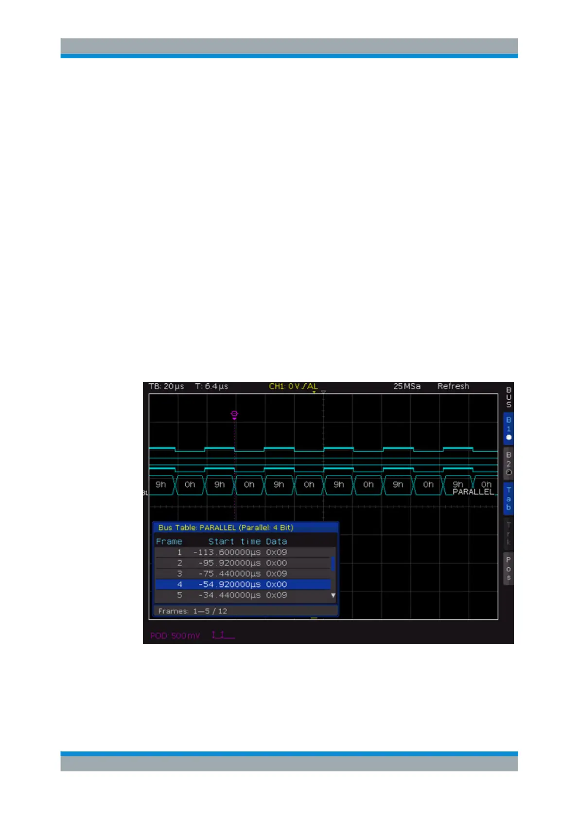
Figure 9-4: Example of a bus table for parallel bus
Using Logic Channels in Buses