Serial Bus Analysis
R&S
®
RTC1000
132User Manual 1335.7352.02 ─ 02
● "SPI" for a 3-wire SPI system.
To configure the SPI bus
1. In the "BUS" menu, press "CONFIGURATION".
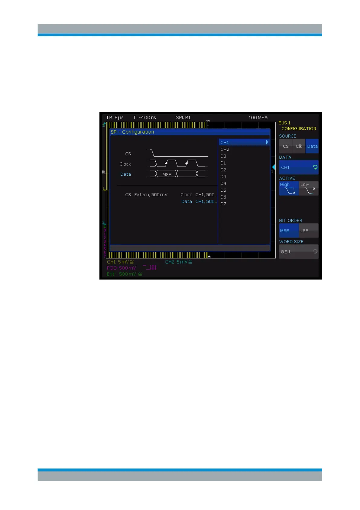
2. Press "SOURCE" to select the chip select ("CS"), clock ("Clk") or data line ("Data").
Figure 11-8: Menu for the definition of an SPI bus
3. Press the second softkey ("CHIP SELECT", "CLOCK", or "DATA". Use the
UNIVERSAL knob to select the source channel.
4. If "CS" is selected, press "ACTIVE" to set high or low active (low active is the
default setting).
5. If "Clk" is selected, press "SLOPE" to decide whether the data is stored with rising
or falling slope (rising slope is the default setting).
6. If "Data" is selected, press "ACTIVE" to assign whether data is high or low active
(high active is the default setting).
7. Press "BIT ORDER" to determine if the data of each message starts with the
"MSB" (most significant bit) or the "LSB" (least significant bit).
8. Press "WORD SIZE" to select with the UNIVERSAL knob how many bits are inclu-
ded in each message. You can select a value between 1 bit and 32 bits.
To configure the SSPI bus
1. In the "BUS" menu, press "CONFIGURATION".
SPI / SSPI BUS (Option R&S
RTC-K1)