Serial Bus Analysis
R&S
®
RTC1000
143User Manual 1335.7352.02 ─ 02
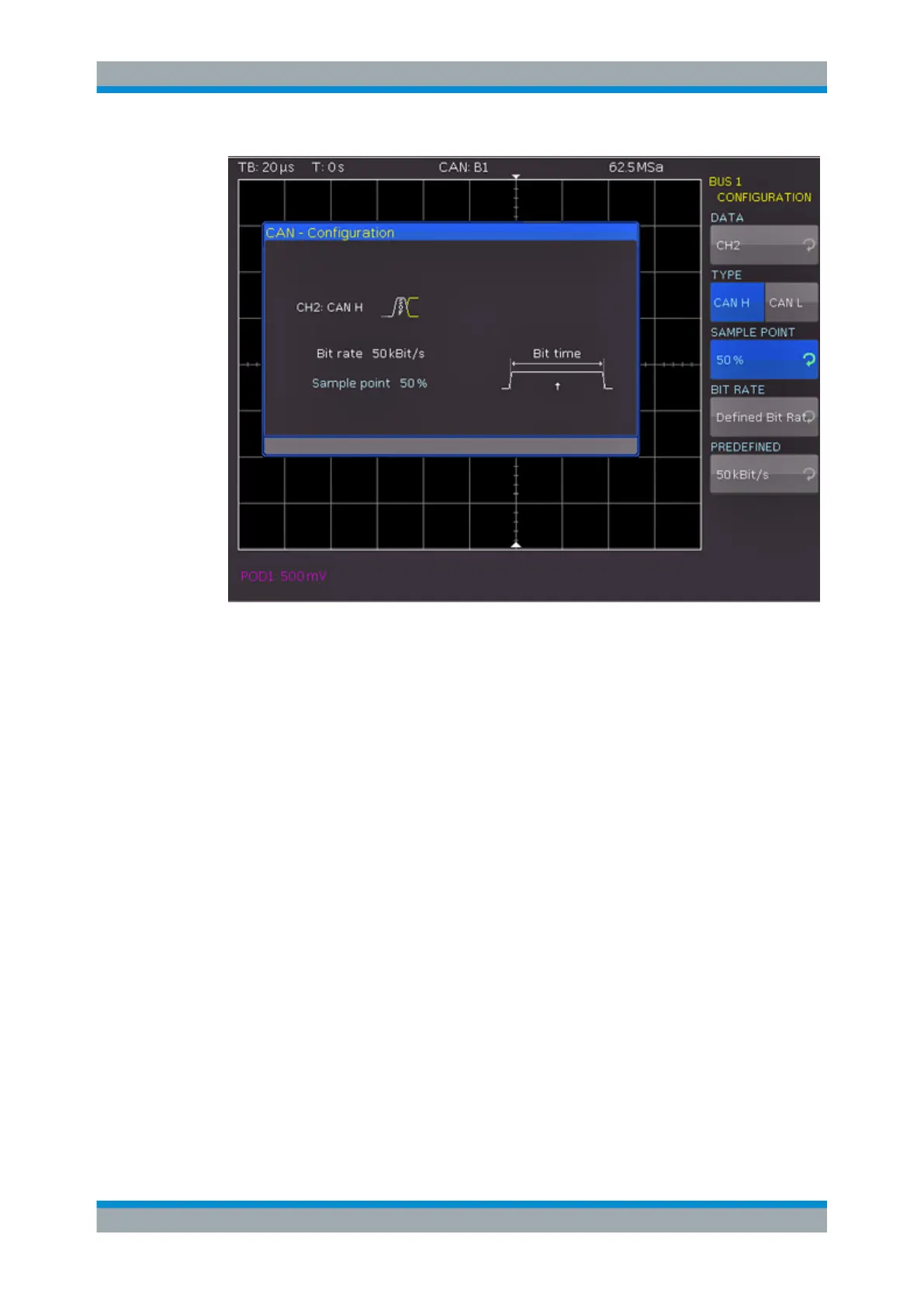
Figure 11-15: CAN bus configuration
DATA
Selects the channel of the data line.
TYPE
Selects the CAN-High or CAN-Low line. CAN uses both lines for differential signal
transmission.
When using a differential probe, select "CAN H" if the positive input of the probe is con-
nected to CAN-High and the negative input to CAN Low. If the probe is connected with
reversed polarity, select "CAN L".
SAMPLE POINT
Sets the position of the sample point within the bit in percent of the nominal bit time.
You can select a value between 25% and 90%.
BIT RATE, USER
The bit rate defines how many bits are sent per second. To select a standard bit rate,
use "BIT RATE". To define a customized rate, use "USER".
11.6.2 CAN Bus Triggering
After the bus configuration is completed, you can trigger on various events.
CAN Bus (Option R&S RTC-K3)