Serial Bus Analysis
R&S
®
RTC1000
150User Manual 1335.7352.02 ─ 02
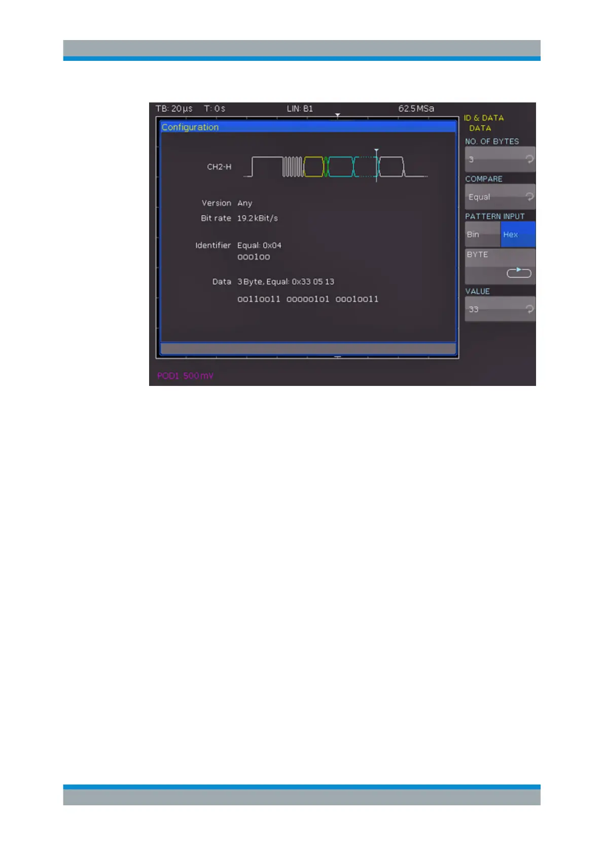
Figure 11-20: LIN data trigger menu
START OF FRAME
Triggers on the stop bit of the synchronizing field.
WAKE UP
Triggers after a wake-up frame.
ERROR
Identifies various errors in a frame. Select one or more error types as trigger condition.
"CRC"
LIN uses a complex checksum calculation (Cyclic Redundancy
Check). The transmitter calculates the CRC and transmits the result
in a CRC sequence. The receiver calculates the CRC in the same
way. An error occurs if the calculated result differs from the received
CRC sequence.
"PARITY"
Triggers on a parity error. Parity bits are bit 6 and bit 7 of the identi-
fier. The correct transfer of the identifier is verified.
"SYNCHRO-
NIZ."
Triggers if the synchronizing field indicates an error.
IDENTIFIER
Triggers on an identifier or identifier range. Configure the following:
●
Compare function: "COMPARE" on page 151.
●
Identifier pattern: "PATTERN INPUT" on page 129.
LIN Bus (Option R&S
RTC-K3)