Waveform Setup
R&S
®
RTC1000
35User Manual 1335.7352.02 ─ 02
1. Select the channel using its CH key.
2. Press the MENU key in the Vertical section.
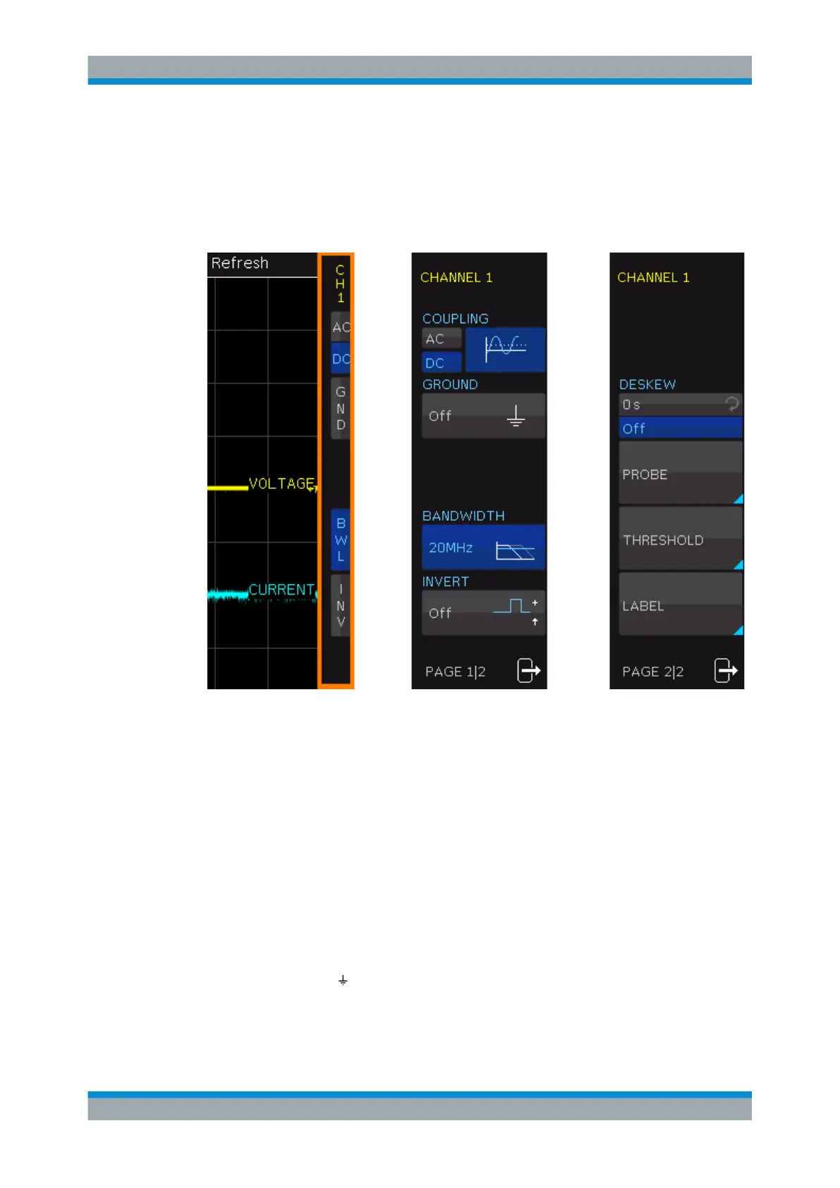
Page 1 of the menu shows the settings of the short menu, page 2 provides further set-
tings.
Figure 4-2: Vertical menus: short menu (left), page 1 and page 2 of the advanced menu
COUPLING
The analog channels have an input impedance of 1 MΩ. The input coupling influences
the signal path between input connector and the following internal signal stage. The
current coupling of each channel is shown in the channel labels below the grid.
"AC"
AC coupling blocks the DC component of the signal so that the wave-
form is centered on zero volts. AC coupling is useful if the DC compo-
nent of a signal is of no interest.
"DC"
With DC coupling, the input signal passes unchanged, all signal com-
ponents are shown.
GROUND (GND)
Connects the input to a virtual ground. All channel data is set to 0 V. Ground connec-
tion is indicated with in the waveform labels. The coupling is not affected by the
ground setting.
Vertical Setup