Waveform Setup
R&S
®
RTC1000
38User Manual 1335.7352.02 ─ 02
Make sure to align passive probes before their first use, after an extended measure-
ment break, or when switching instruments or channels.
Two connector pins for compensation are located at the front panel. The left pin is on
ground level. The next pin supplies a square wave signal for the adjustment.
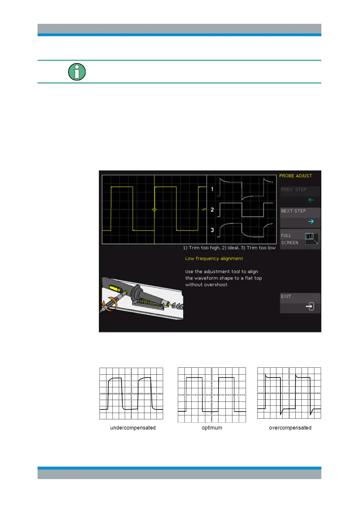
To perform probe compensation using the wizard
1. Press the SETUP key in the General section.
2. Press the "PROBE ADJUST" softkey.
3. Follow the instructions of the wizard. It guides you through the compensation proc-
ess.
4. Use the compensation trimmer of the probe to get optimum square wave response.
For details, refer to the documentation of your probe.
The compensation is performed at 1 kHz (LF) and 1 MHz (HF).
Vertical Setup