Trigger
R&S
®
RTC1000
53User Manual 1335.7352.02 ─ 02
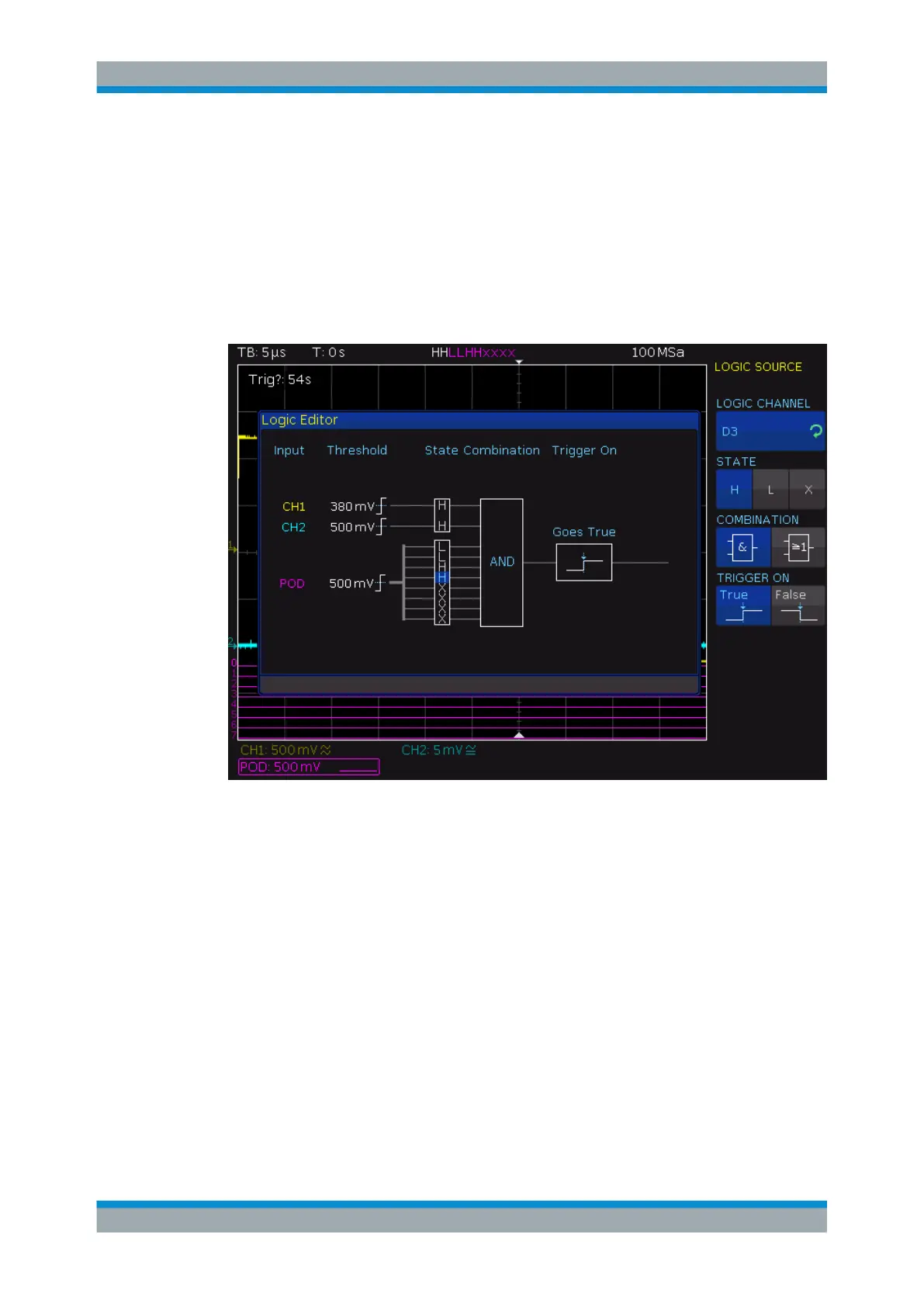
3. Turn the Universal knob to select the "LOGIC CHANNEL" for which you want to set
the logic state.
4. Press "STATE" repeatedly until the required state is selected.
5. Repeat steps 3 and 4 for each channel of the pattern.
6. Select the logic "COMBINATION" of the channels.
7. Select whether you want to trigger on the true or false pattern: "TRIGGER ON".
Figure 5-1: Logic trigger pattern setup
LOGIC CHANNEL
Selects the channel for which you want to set the logic state. The setting is always
active.
STATE
Selects the channel state: high ("H"), low ("L") or don't care ("X").
COMBINATION
Sets the logic combination of the channels:
"AND"
The states of all channels must be met simultaneously to produce a
logic high ("H", true) as a result.
"OR"
At least one of the defined states must be met to produce a logic high
("H", true) as a result.
Logic Trigger