6-14 Mains and Supply Voltage Connection Rexroth EcoDrive Cs Drives
DOK-ECODR3-DKC**.3-CS*-PR02-EN-P
6.4 Selecting Q1 Fuse and K1 Contactor
• Several controllers can be operated on a single fuse and mains
contactor. The phase currents and inrush currents of the individual
drives must then simply be added up.
• If a transformer is used, then the fuses and contactors must be
installed on the primary side.
• When selecting the mains contactor (power circuit-breaker), observe
the fuse characteristics to make sure that the relatively strong inrush
current does not cause the fuse to respond.
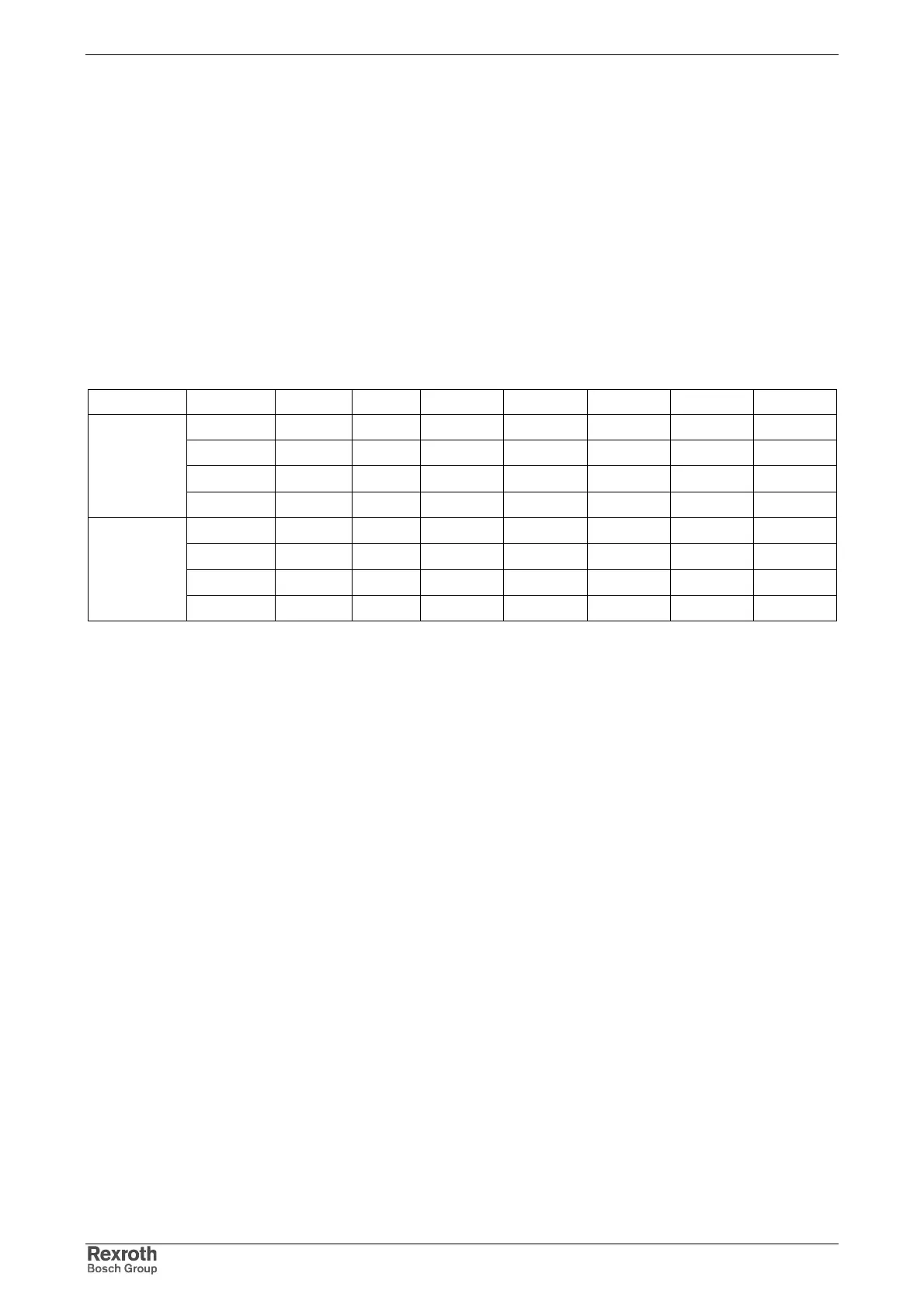
With the known technical data of the devices and the above formulas
there are the following values:
Connection U
Netz_max
[V] P
mech
[W]
η [%]
P
DC
[W] S
N1
[VA] I
Ein
[A] I
N1
[A] T [ms]
264 100 61 140.3 400 79.2 1.5 2.54
264 200 71 253.2 700 79.2 2.7 3.8
264 400 83 457.1 1400 79.2 5.3 3.8
single-phase
264 750 90 796.2 2165 79.2 8.2 3.8
264 100 61 140.3 400 79.2 0.9 2.54
264 200 71 253.2 700 79.2 1.5 3.8
264 400 83 457.1 1400 79.2 3.1 3.8
three-phase
264 750 90 796.2 2165 79.2 4.7 3.8
U
Netz_max:
Maximum admissible mains input voltage
P
mech
: Power at the driven shaft of the motor
η: Efficiency
P
DC
: Continuous DC bus power
S
N1
: Mains connection power
I
Ein
: Inrush current
I
N1
: Phase current of the mains
T: Time constant of RC element (T = R
Softstart
x C
Zwischenkreis
)
Fig. 6-18: Overview of phase currents and inrush current peaks of the devices
for single-phase and three-phase operation
Therefore, the following criteria have to be taken into account when
selecting the mains contactor:
•
cable cross section of the supply feeders
The supply feeders of the drive controllers have to be fused by means
of the circuit breakers. The maximum possible wire cross section at
the terminal connector is 2.0 mm
2
(-> max. 16 A when cross-section is
1.5 mm
2
).
•
mains current consumption at continuous operation in nominal
working point
It must be possible for the mains-side phase current I
N1
to be
continuously flowing without the fuse triggering.
•
duration of maximum inrush current and device peak current
It must be possible for the inrush current I
Ein
to flow at least for the time
t = 5*T = 15 ms without the fuse triggering. Therefore use slow fuses!
Notes
Courtesy of CMA/Flodyne/Hydradyne ▪ Motion Control ▪ Hydraulic ▪ Pneumatic ▪ Electrical ▪ Mechanical ▪ (800) 426-5480 ▪ www.cmafh.com