5-12 Electrical Connections Rexroth EcoDrive Cs Drives
DOK-ECODR3-DKC**.3-CS*-PR02-EN-P
X4, Encoder
Technical Data of the Terminal Connector
TX
RX
S20
2
1
ON
X4
X5
X6
9
8
7
6
5
4
3
2
1
9
8
7
6
5
4
3
2
1
ADDRESS
NODE
00
Rexroth
ECODRIVE
Cs
S1
H1
S2
S3
LINE ERROR
X20
X21
X4
X5_3 X5_2 X5_1
INPUTíF200V-240V
X3 X2 X1
X6
schnittstellen_X4.fh7
X4
65
43
21
x4_molex.fh7
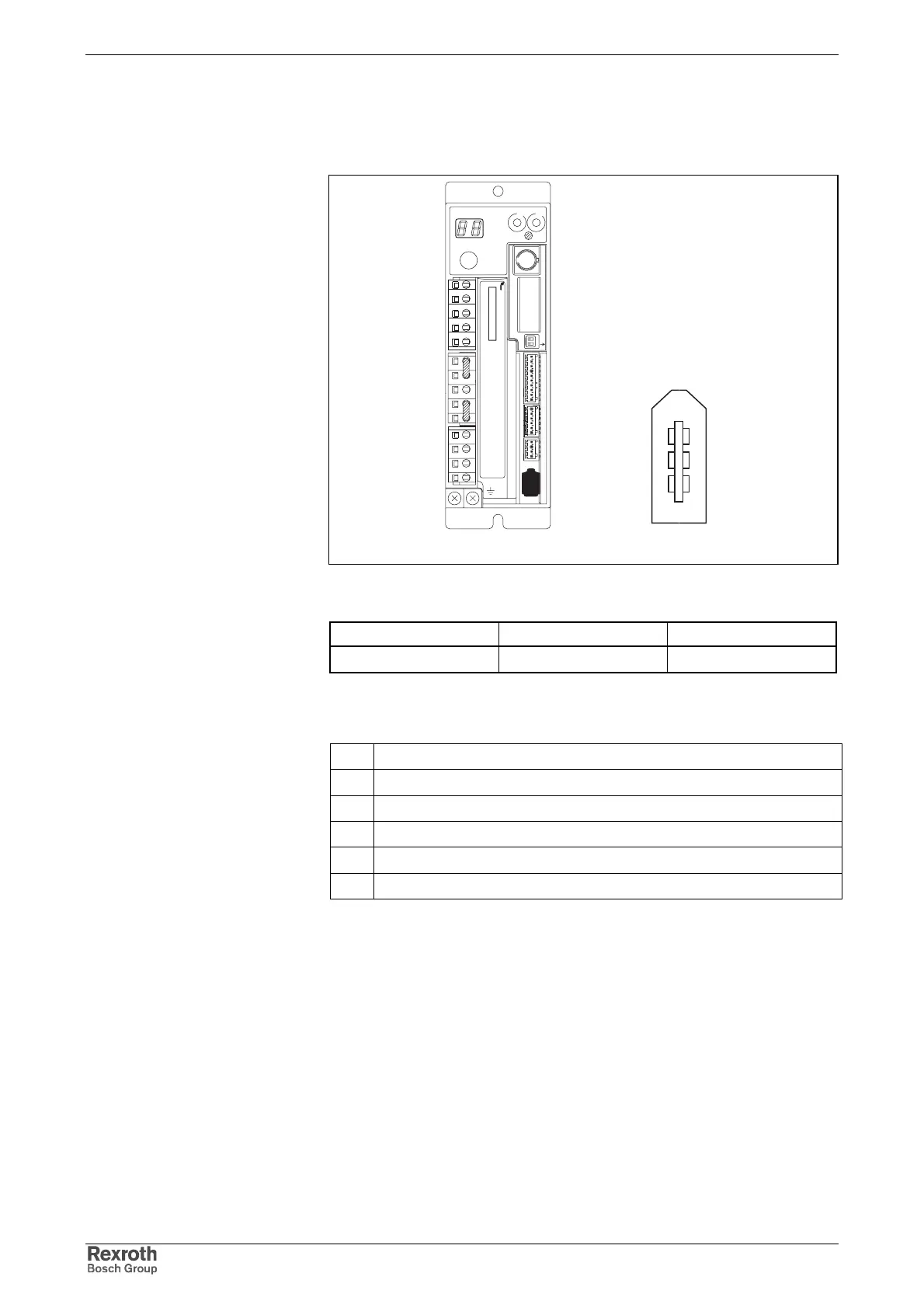
Fig. 5-21: Terminal connector X4
Type Number of poles Type of design
socket 6 socket on device
Fig. 5-22: Design
Connectors
1 encoder voltage supply output (5V)
2 encoder voltage supply output (0V)
3 positive pole of battery*
4 negative pole of battery*
5 encoder signal input (PS)
6 encoder signal input (PS negated)
* battery not required if the absolute encoder is used as an incremental encoder;
the battery is set into the drive controller (see chapter "Motors" → "Startup,
Operation, and Maintenance" → "Maintenance" → "Battery")
Fig. 5-23: Encoder connection
shield is grounded by means of shielding plate in connector
maximum allowed length of encoder cable: 40 m
data for encoder cable: see chapter 10.1
Graphic Representation
Design
Encoder Connection
Shield Connection
Encoder Cable
Courtesy of CMA/Flodyne/Hydradyne ▪ Motion Control ▪ Hydraulic ▪ Pneumatic ▪ Electrical ▪ Mechanical ▪ (800) 426-5480 ▪ www.cmafh.com