Rexroth EcoDrive Cs Drives Technical Data (Drive Controllers) 4-9
DOK-ECODR3-DKC**.3-CS*-PR02-EN-P
4.4 Electrical Data
Power Section
Designation Symbol Unit DKC**.3
operating mode on the mains single-phase* three-phase
mains input voltage U
LN
V 1 x AC 3 x AC
200 - 240 +10%, -15%
mains frequency f
LN
Hz 50/60
connected load S
LN
kVA
-004: 0.4
-008: 0.7
-012: 1.4
-018: 2.1
-004: 0.4
-008: 0.7
-012: 1.4
-018: 2.4
nominal inrush current**
(depending on mains input voltage)
I
L,cont
AI
EIN1
= U
LN.max
*1,414/R
DC(Start);
see chapter 6.3 Inrush Current and Mains Phase
Current
nominal continuous input current**
(depending on mains input voltage
and supply)
I
L,max
(On) A
-004: 1.1
-008: 1.3
-012: 2.2
-018: 5.3
-004: 0.7
-008: 1.1
-012: 1.8
-018: 4.0
soft-start resistor R
DC(Start)
Ohm 4.7
continuous power soft-start resistor P
DC(Start)
W17
switching frequency (selectable) f
S
kHz 4 and 8
continuous output current ** I
out_eff cont2
A
-004: 1.0
-008: 1.6
-012: 2.5
-018: 3.4
-004: 1.0
-008: 1.6
-012: 2.5
-018: 4.3
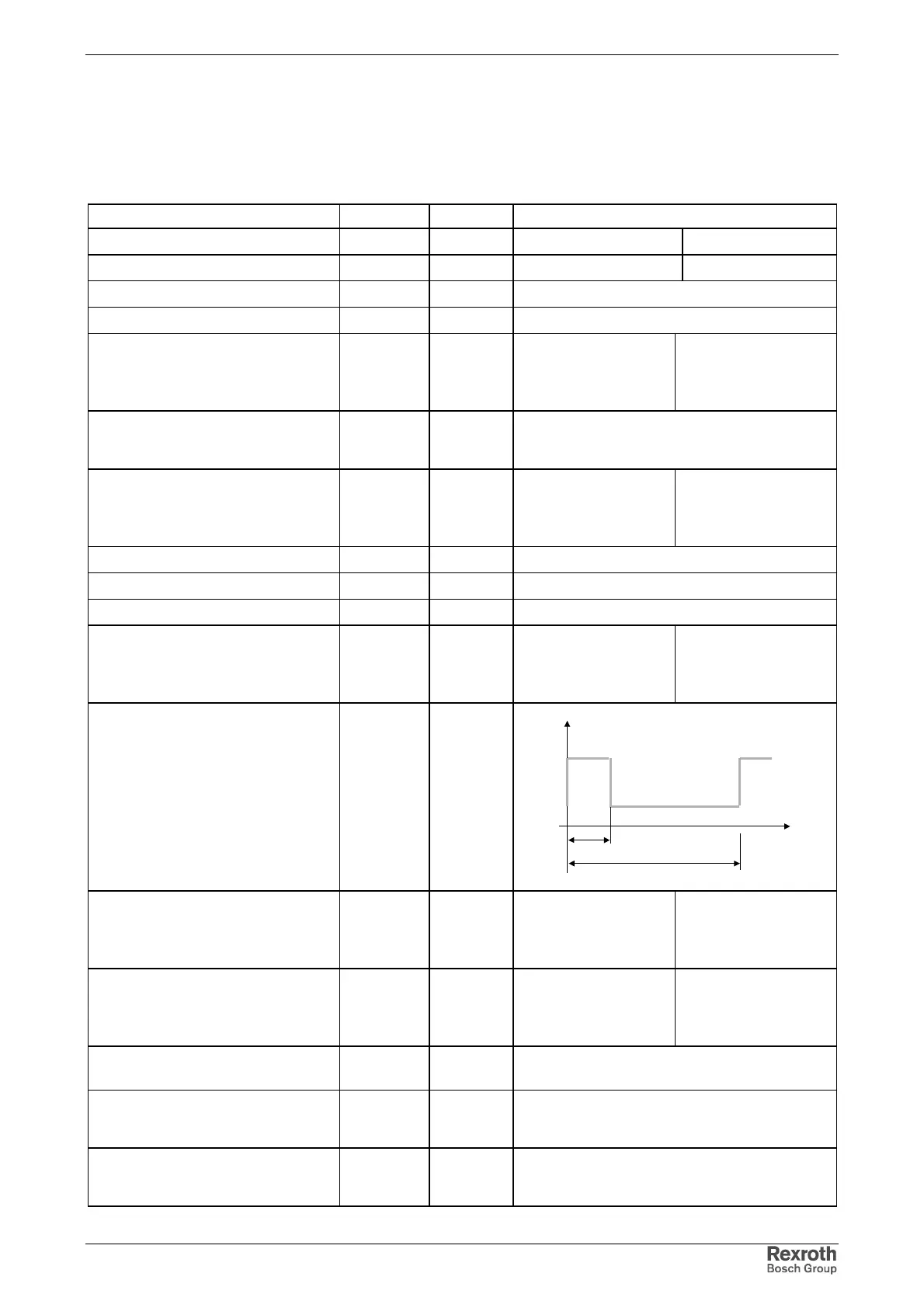
characteristic curve output current
T
I
t
I
t
I
maximum output current**,
t=400ms;
I
out_eff _cont1
=0A
I
out_eff max
A
-004: 3.0
-008: 4.8
-012: 7.5
-018: 10.3
-004: 3.0
-008: 4.8
-012: 7.5
-018: 12.9
base load current at maximum
current**;
t=400ms; T=4s
I
out_eff cont1
(
I
out_eff max)
A
-004: 0.4
-008: 0.5
-012: 0.9
-018: 1.1
-004: 0.4
-008: 0.5
-012: 0.9
-018: 1.4
output frequency range f
out
Hz
-004 ... -012: 0 ... 333.3
-018: 0 ... 300
power dissipation of the device
(without internal continuous braking
resistor power at 8 kHz)
P
VDiss,Drive
W
-004: 24.7
-008: 31.3
power dissipation of the device
(without internal continuous braking
resistor power at 4 kHz)
P
Diss,Drive
W
-012: 34.5
-018: 41.9
Courtesy of CMA/Flodyne/Hydradyne ▪ Motion Control ▪ Hydraulic ▪ Pneumatic ▪ Electrical ▪ Mechanical ▪ (800) 426-5480 ▪ www.cmafh.com