Rexroth EcoDrive Cs Drives Electrical Connections 5-15
DOK-ECODR3-DKC**.3-CS*-PR02-EN-P
X5_2: Digital Outputs
Technical Data of the Terminal Connector
schnittstellen_X52.fh7
TX
RX
S20
2
1
ON
X4
X5
X6
9
8
7
6
5
4
3
2
1
9
8
7
6
5
4
3
2
1
ADDRESS
NODE
00
Rexroth
ECODRIVE
Cs
S1
H1
S2
S3
LINE ERROR
X20
X21
X4
X5_3 X5_2 X5_1
INPUTíF200V-240V
X3 X2 X1
X6
Bb2
Bb1
OUT7
OUT8
0V_ext
+24V_ext
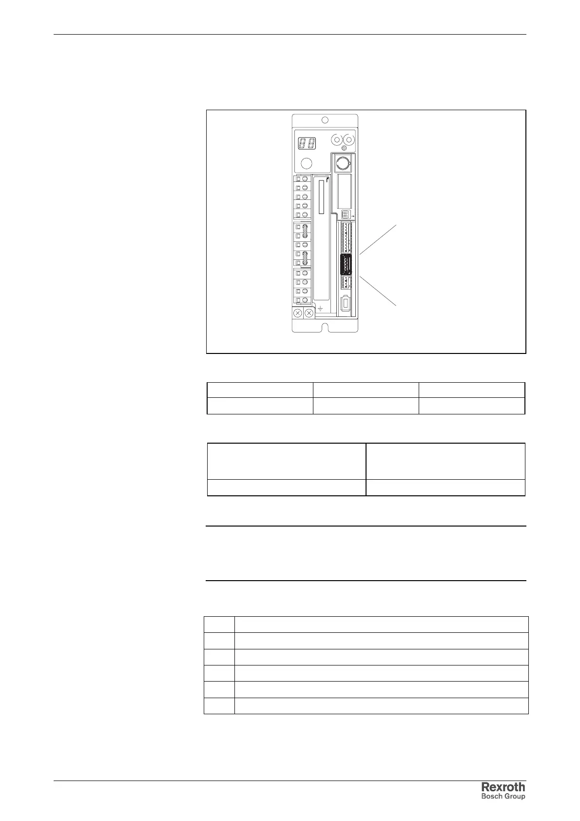
Fig. 5-30: Terminal connector X5_2
Type Number of poles Type of design
spring tension 6 socket on connector
Fig. 5-31: Design
Cross section
single-core
[mm²]
Cross section in AWG
gauge No.
0,25 - 0.5 23 - 20
Fig. 5-32: Connection cross section
Note: The digital outputs can be configured by means of the "Digital
outputs" firmware function in conjunction with the freely
configurable signal status word. The following paragraph
describes the default configuration.
Connections (Default Configuration)
6 "ready for operation" contact (relay output; N/O contact)
5 "ready for operation" contact (relay output; N/O contact)
4OUT7
3OUT8
20 V ext
1 +24 V ext
Fig. 5-33: Control outputs
Graphic Representation
Design
Connection Cross Section
Connection of Digital Outputs
Courtesy of CMA/Flodyne/Hydradyne ▪ Motion Control ▪ Hydraulic ▪ Pneumatic ▪ Electrical ▪ Mechanical ▪ (800) 426-5480 ▪ www.cmafh.com