Rexroth EcoDrive Cs Drives Electrical Connections 5-1
DOK-ECODR3-DKC**.3-CS*-PR02-EN-P
5 Electrical Connections
5.1 Connections Independent of the Device
Views of the Devices and Terminal Connector Designations
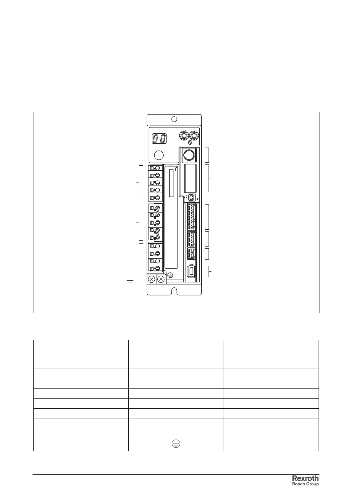
Front View
schnittstellen_overview.fh7
X6
X*
X5_1
X5_2
X5_3
X4
X1
X2
X3
TX
RX
S20
2
1
ON
X4
X5
X6
ADDRESS
NODE
Rexroth
EcoDrive Cs
S1
H1
S2
S3
LINE ERROR
X20
X21
X4
X5_3 X5_2 X5_1
INPUT : 200V-240V
X3 X2 X1
X6
W
V
U
RB2
RB3
RB1
DL2
DL1
L2C
L1C
L3
L2 L1
9
8
7
6
5
4
3
2
1
9
8
7
6
5
4
3
2
1
0 0
Fig. 5-1: Front view with terminal connector designations
Description of connections:
Connection Designation See page
mains, control voltage X1 5-5
reactance coil, braking resistor X2 5-6
motor X3 5-9
encoder X4 5-12
digital inputs X5_1 5-13
digital outputs X5_2 5-15
holding brake X5_3 5-18
RS232 X6 5-21
master communication X* 5-23
ground 5-11
Fig. 5-2: Connections
Courtesy of CMA/Flodyne/Hydradyne ▪ Motion Control ▪ Hydraulic ▪ Pneumatic ▪ Electrical ▪ Mechanical ▪ (800) 426-5480 ▪ www.cmafh.com