Rexroth EcoDrive Cs Drives Motors 8-27
DOK-ECODR3-DKC**.3-CS*-PR02-EN-P
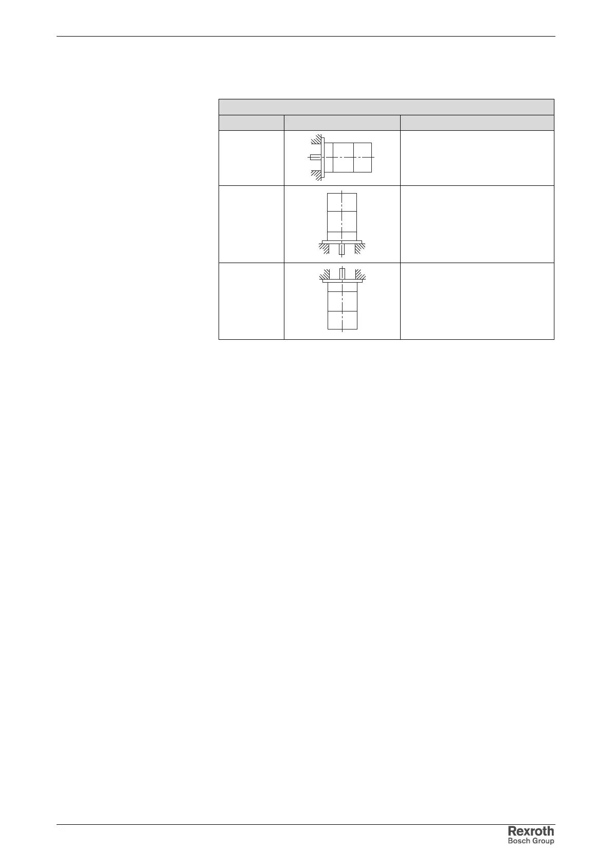
Design and Installation Positions
Permissible types of installation
Description Sketch Setup
IM B5
Flange attached on the drive side
of the flange
IM V1
Flange attached on the drive side
of the flange; drive side pointing
down
IM V3
Flange attached on the drive side
of the flange; drive side pointing up
Fig. 8-37: Mounting position
Courtesy of CMA/Flodyne/Hydradyne ▪ Motion Control ▪ Hydraulic ▪ Pneumatic ▪ Electrical ▪ Mechanical ▪ (800) 426-5480 ▪ www.cmafh.com