Rexroth EcoDrive Cs Drives Electrical Connections 5-3
DOK-ECODR3-DKC**.3-CS*-PR02-EN-P
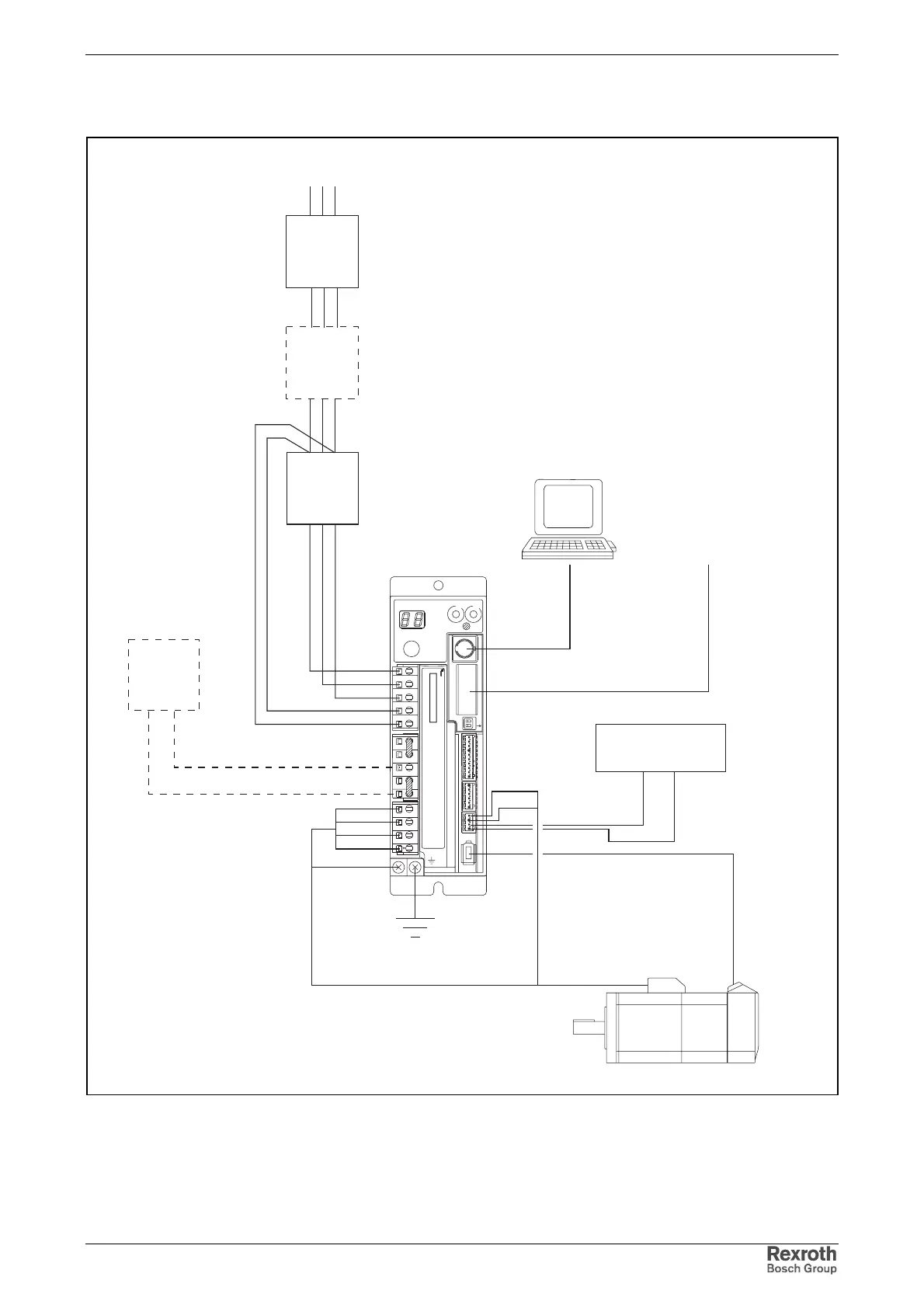
Schematic Overall Connection Diagram
anschlussplan_gesamt_en.fh7
TX
RX
S20
2
1
ON
X4
X5
X6
W
V
U
RB2
RB3
RB1
DL2
DL1
L2C
L1C
L3
L2 L1
9
8
7
6
5
4
3
2
1
9
8
7
6
5
4
3
2
1
ADDRESS
NODE
00
Rexroth
ECODRIVE
Cs
S1
H1
S2
S3
LINE ERROR
X20
X21
X4
X5_3 X5_2 X5_1
INPUTíF200V-240V
X3 X2 X1
X6
braking
resistor
RS232
master
communication
encoder
cable
motor cable
L1
L2
L3
L1C
L2C
RB1
RB2
U
0V
W
Ground
Shield
voltage supply
of holding brake
24V
BR+
BR-
V
trans-
former
L1 L2 L3
L1 N (1ph)
(3ph)
necessary, when mains voltage > 240 V
necessary
magnetic
contactor
optional
RB3
mains
filter
Fig. 5-4: Schematic overall connection diagram
Concerning description of connections: see table on page 5-1.
Concerning cables: see chapter 10.1
Courtesy of CMA/Flodyne/Hydradyne ▪ Motion Control ▪ Hydraulic ▪ Pneumatic ▪ Electrical ▪ Mechanical ▪ (800) 426-5480 ▪ www.cmafh.com