5-2 Electrical Connections Rexroth EcoDrive Cs Drives
DOK-ECODR3-DKC**.3-CS*-PR02-EN-P
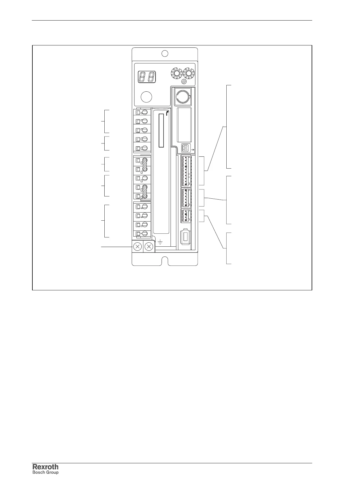
Pin Assignments
schnittstellen_overview_text_en.fh7
L1
L2
L3
L1C
L2C
DL1
DL2
RB1
RB3
RB2
10
9
8
7
6
5
4
3
2
1
6
5
4
3
2
1
4
3
2
1
mains voltage
control voltage
reactance coil
braking resistor
U
V
W
ground
motor
ground
BR-
BR+
+24V_ext_brake
0V_ext_brake
10
1
6
1
1
4
OUT1
IN7
0V_ext
0V_ext
IN6
IN5
IN4
IN3
IN2
IN1
Bb2
Bb1
OUT7
OUT8
0V_ext
+24V_ext
TX
RX
S20
2
1
ON
X4
X5
X6
ADDRESS
NODE
Rexroth
ECODRIVE
Cs
S1
H1
S2
S3
LINE ERROR
X20
X21
X4
X5_3 X5_2 X5_1
INPUTíF200V-240V
X3 X2 X1
X6
W
V
U
RB2
RB3
RB1
DL2
DL1
L2C
L1C
L3
L2 L1
9
8
7
6
5
4
3
2
1
9
8
7
6
5
4
3
2
1
0 0
Fig. 5-3: Pin assignments of the interfaces
The digital inputs (IN1…7) and outputs (OUT1…3) are free configurable.
At delivery the inputs and outputs are preconfigured (see page 5-13
onward).
Courtesy of CMA/Flodyne/Hydradyne ▪ Motion Control ▪ Hydraulic ▪ Pneumatic ▪ Electrical ▪ Mechanical ▪ (800) 426-5480 ▪ www.cmafh.com