Rexroth EcoDrive Cs Drives Electrical Connections 5-5
DOK-ECODR3-DKC**.3-CS*-PR02-EN-P
X1, Mains and Control Voltage
DANGER
Lethal electric shock caused by live parts with
more than 50 V!
⇒
Before starting to work on the drive controller switch
off the voltage supply via the main switch or the
circuit breaker.
⇒
Always mount or dismount both connectors (motor
connection and mains connection) at the drive
controller.
⇒
Observe the notes in the "Safety Instructions for
Electric Drives and Controls" chapter.
Technical Data of the Terminal Connector
schnittstellen_X1.fh7
TX
RX
S20
2
1
ON
X4
X5
X6
W
V
U
RB2
RB3
RB1
DL2
DL1
9
8
7
6
5
4
3
2
1
9
8
7
6
5
4
3
2
1
ADDRESS
NODE
00
Rexroth
ECODRIVE
Cs
S1
H1
S2
S3
LINE ERROR
X20
X21
X4
X5_3 X5_2 X5_1
INPUTíF200V-240V
X3 X2 X1
X6
L2C
L1C
L3
L2 L1
L1
L2
L3
L1C
L2C
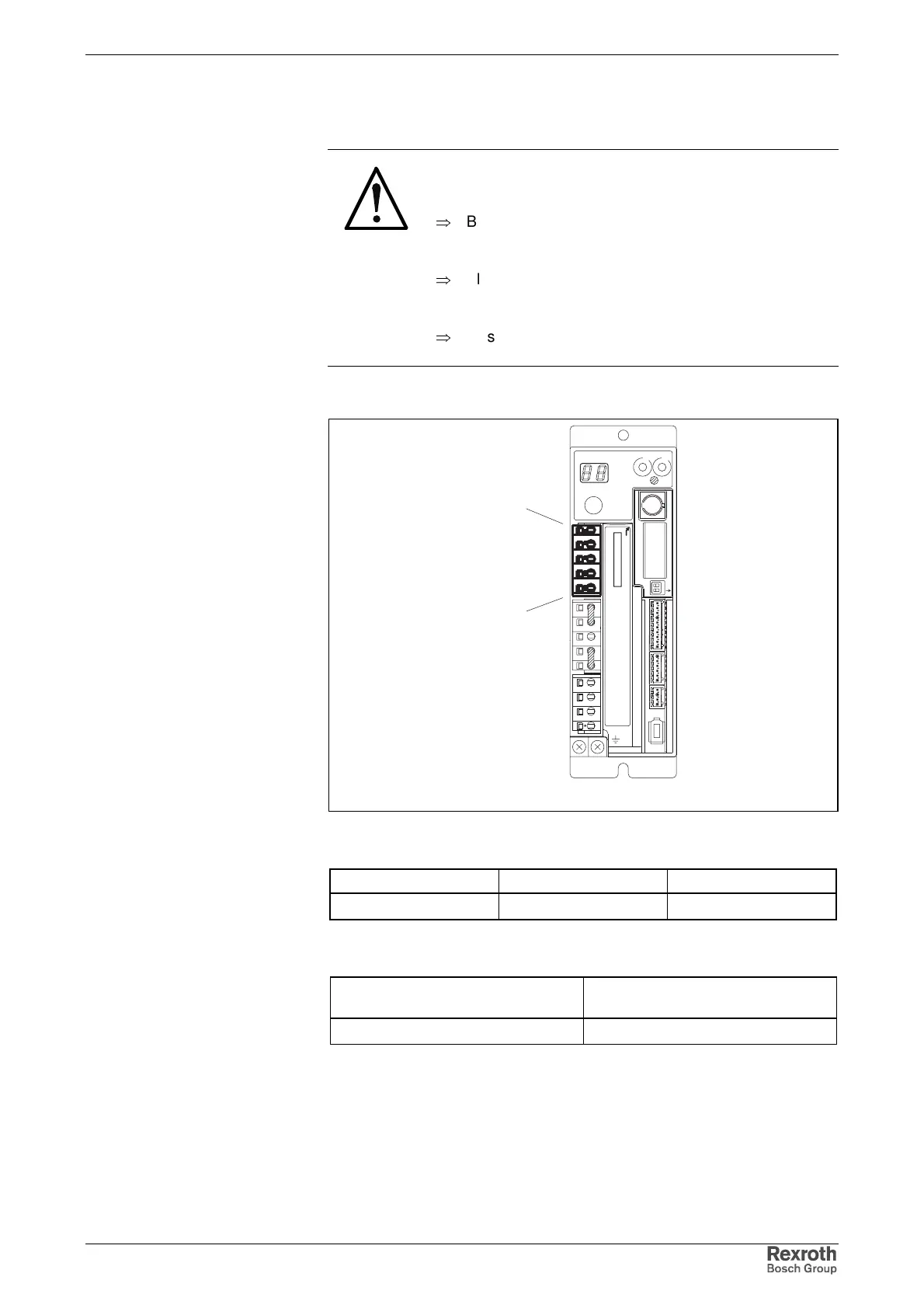
Fig. 5-6: Terminal connector X1
Type Number of poles Type of design
spring tension 5 socket on connector
Fig. 5-7: Design
Max. connectable cross section
[mm²]
Cross section in AWG
gauge No.
2.5 12
Fig. 5-8: Connection cross section
Connection of Mains and Control Voltage
See chapter 6 Mains and Supply Voltage Connection
Graphic Representation
Design
Connection Cross Section
Courtesy of CMA/Flodyne/Hydradyne ▪ Motion Control ▪ Hydraulic ▪ Pneumatic ▪ Electrical ▪ Mechanical ▪ (800) 426-5480 ▪ www.cmafh.com