4-16 Technical Data (Drive Controllers) Rexroth EcoDrive Cs Drives
DOK-ECODR3-DKC**.3-CS*-PR02-EN-P
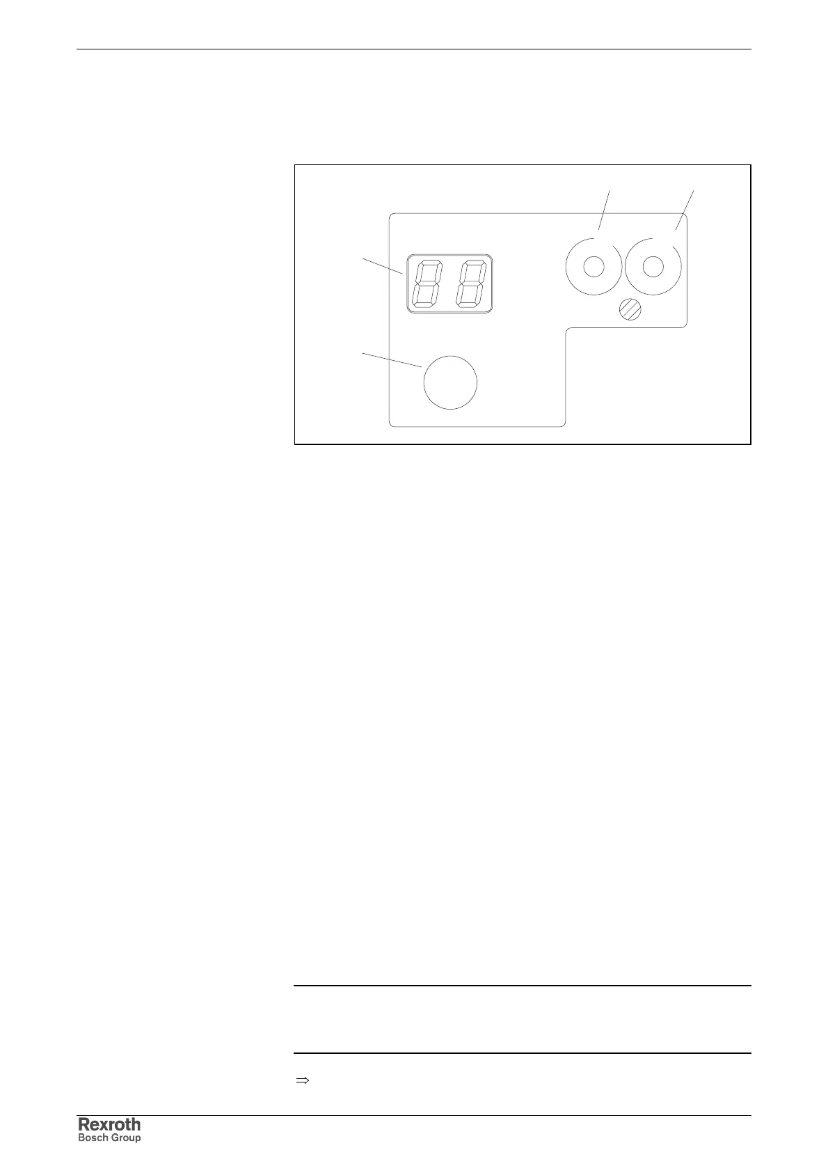
4.5 Control and Display Elements (H1, S1, S2, S3)
panel.fh7
H1
S1
Cs
ECODRIVE
Rexroth
S3
S2
00
NODE
ADDRESS
1
2
3
4
5
6
7
8
9
1
2
3
4
5
6
7
8
9
LINE ERROR
H1
S1
S3 S2
Fig. 4-16: H1: diagnostic display, S1: button, S2, S3: address switch
H1 (Diagnostic Display)
For display of the diagnostic messages (errors and operating states).
S1 (Button)
Depending on the situation the S1 button has different functions:
• Normal operation:
Reset button for resetting error diagnoses.
• Device initialization (after switching on the supply):
button for activating the bootstrap loader (firmware update)
• With baud rate scan:
button for activating the manual mode
• Commissioning:
During baud rate scan press button for at least 5 seconds to get into
the setting mode.
S2, S3 (Address Switch)
Switch for setting the drive address.
The address of the drive can be set by means of two ten-stage switches.
The address can be a number from 1 to 99.
Example:
switch setting S3 = 9 (tens unit)
switch setting S2 = 1 (unit)
drive address = 9 * 10 + 1 = 91
Note: The unit is supplied with the address not being pre-set.
The setting of switches S2 and S3 depends on the type series,
the firmware which is used or the desired drive address.
⇒
See Functional Description of firmware
Address Switch S2, S3
Drive Address
Courtesy of CMA/Flodyne/Hydradyne ▪ Motion Control ▪ Hydraulic ▪ Pneumatic ▪ Electrical ▪ Mechanical ▪ (800) 426-5480 ▪ www.cmafh.com