8-30 Motors Rexroth EcoDrive Cs Drives
DOK-ECODR3-DKC**.3-CS*-PR02-EN-P
Please observe the instructions on putting the holding brakes into
operation described in the chapter entitled “Startup, Operation, and
Maintenance”.
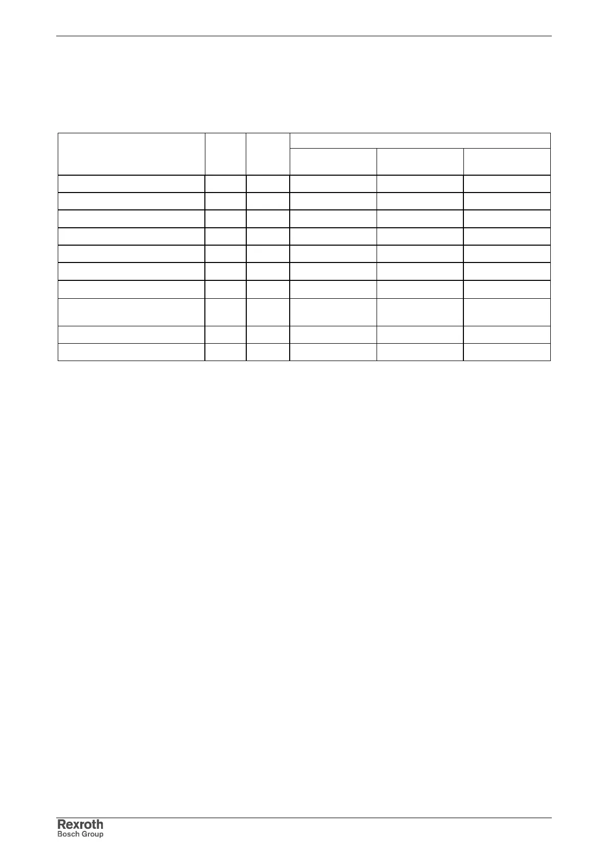
Data
Holding brake dataDesignation Symbol Unit
MSM020B MSM030B;
MSM030C
MSM040B
holding torque M
4
Nm 0.29 1.27 2.45
tripping voltage V > 1 > 1 > 1
rated voltage U
N
V
24 ±10% 24 ±10% 24 ±10%
rated current I
N
A 0.26 0.36 0.43
moment of inertia J
B
kgm
2
0.003 0.03 0.09
clamping delay t
1
ms
≤ 25 ≤ 50 ≤ 60
release delay t
2
ms
≤ 20 ≤ 15 ≤ 15
allowed braking energy (once per
braking operation)
J 39.2 137 196
allowed braking energy (total) J 4.9 x 10
3
44.1 x 10
3
147 x 10
3
allowed angular acceleration rad/s
2
10000 10000 10000
all data based on an ambient temperature of 20 °C
Fig. 8-41: Technical data of holding brake
• The above values are typical values, except for holding torque, tripping
voltage and rated voltage.
• When the motor was moved the play of the brake is ±1°
or less.
• The power supply of the holding brake is realized externally.
• Maximum number of acceleration and braking processes with the
highest allowed angular acceleration: 10 million.
Output Shaft and Motor Bearing
Plain shaft
The standard design recommended for MSM motors provides a friction-
locked shaft-hub connection without play and excellent running
smoothness. Use clamping sets, clamping sleeves or clamping elements
to couple the machine elements to be driven.
Output shaft with key
The optional key permits keyed transmission of torques with constant
direction, with low requirements for the shaft-hub connection.
Courtesy of CMA/Flodyne/Hydradyne ▪ Motion Control ▪ Hydraulic ▪ Pneumatic ▪ Electrical ▪ Mechanical ▪ (800) 426-5480 ▪ www.cmafh.com