7-2 Designing the Control Cabinet Rexroth EcoDrive Cs Drives
DOK-ECODR3-DKC**.3-CS*-PR02-EN-P
CAUTION
High temperature
Risk of damage to temperature-sensitive control
cabinet components in the area of the cooling air
outlet.
⇒
Make sure the distances are sufficient.
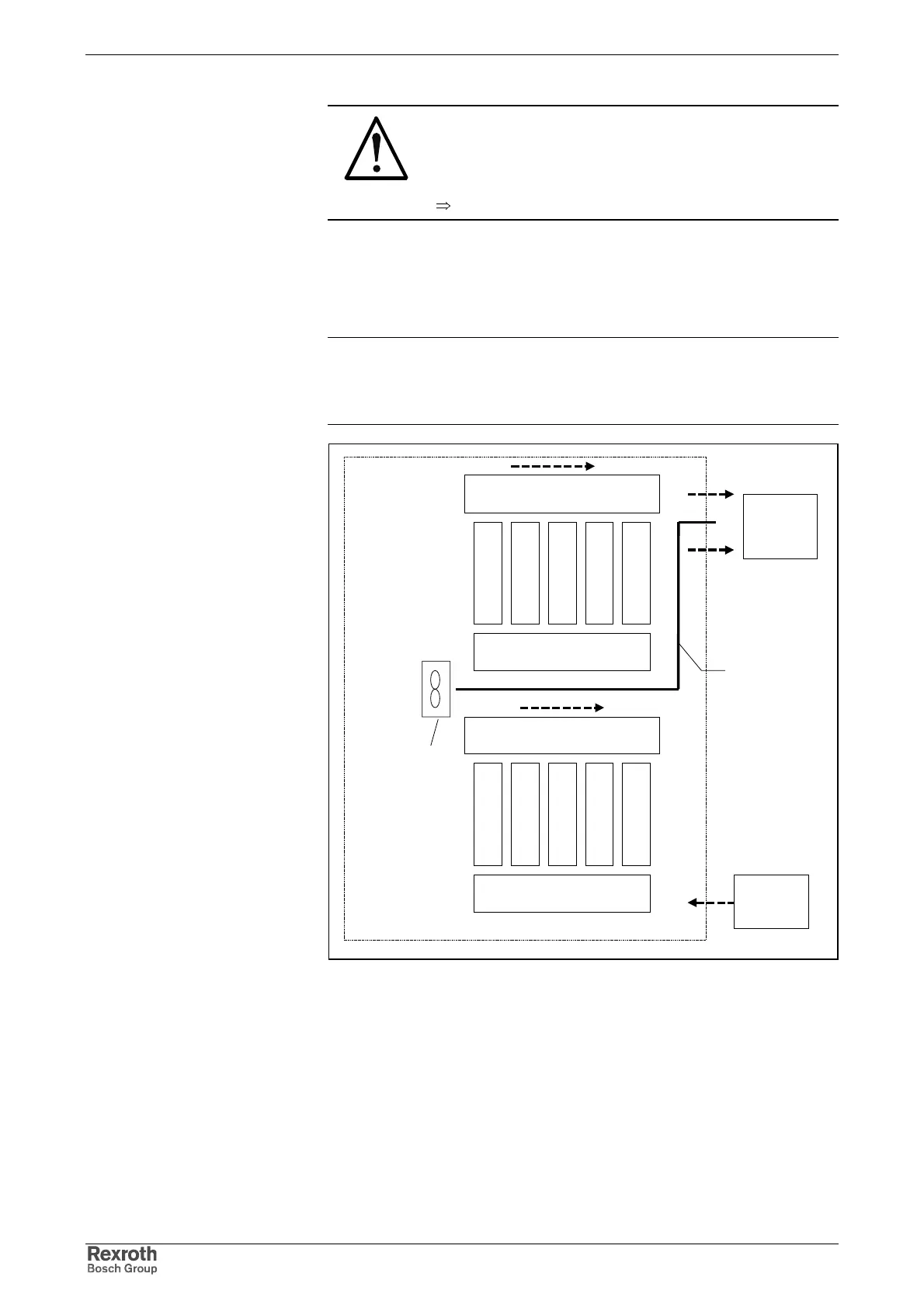
Arranging the Components in the Control Cabinet
Control Cabinet with Multiple Line Structure
Note: In particular when arranging components in multiple lines
within the control cabinet, it is important to observe their max.
air inlet temperature (see technical data) and, if necessary, to
mount air baffles with blowers used for this specific purpose.
For example:
air baffle
Additional
blower
Discharge direction of the
warmed air in the flow-off area
Discharge direction of the
warmed air in the flow-off area
Inlet area of the cooling air for
the upper device line
Inlet area of the cooling air for
the lower device line
Exhaust air
to the air
conditioner
Supply air
from the air
conditioner
Fig. 7-2: Example of arrangement for multiple line structure
Courtesy of CMA/Flodyne/Hydradyne ▪ Motion Control ▪ Hydraulic ▪ Pneumatic ▪ Electrical ▪ Mechanical ▪ (800) 426-5480 ▪ www.cmafh.com