5-14 Electrical Connections Rexroth EcoDrive Cs Drives
DOK-ECODR3-DKC**.3-CS*-PR02-EN-P
Connections
10 OUT1
9IN7
80 V ext
(connect to negative pole of external 24 V power supply)
70 V ext
(connect to negative pole of external 24 V power supply)
6IN6
5IN5
4IN4
3IN3
2IN2
1IN1
Fig. 5-27: Digital inputs
Note: Default configuration: see Functional Description of firmware.
Note: As the digital inputs are galvanically separated, the reference
conductor of the separate power supply unit has to be
connected to GND.
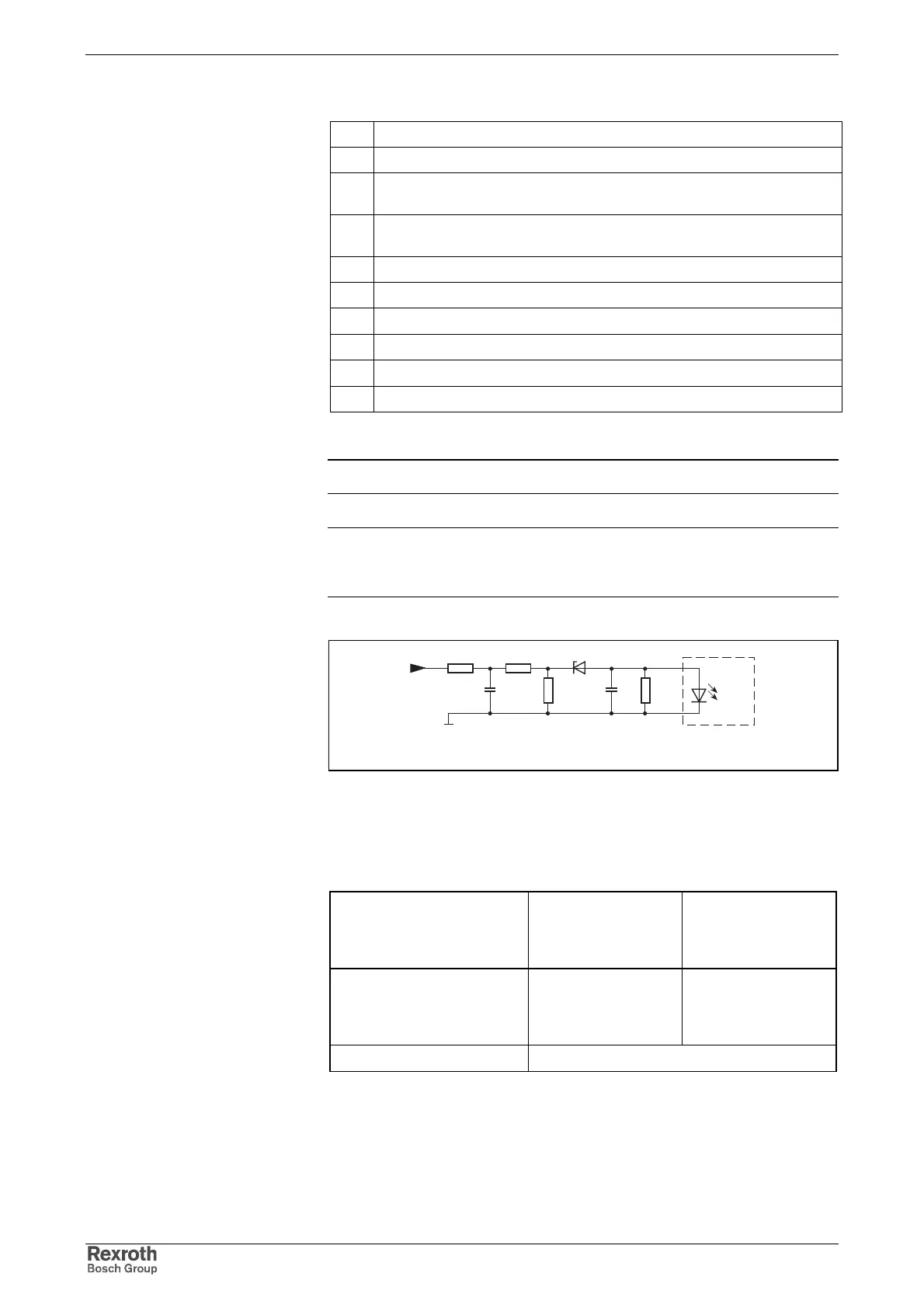
X5_1_dig_ein_prinzip.fh7
R1 5V6
0 V
ext
R1
R3R2C1 C1
R1: 1k
R2: 10k
R3: 4k7
C1: no data
Fig. 5-28: Input circuitry (block diagram)
voltage:
High
Low
min.
5 V
-3 V
max.
30 V
11 V
current:
High
Low
min.
6 mA
no data
max.
30 mA
30 mA
input resistance 12 kOhm
Fig. 5-29: Inputs
Digital Input Connection
Input circuitry of Digital Inputs
Inputs of Digital Inputs
Courtesy of CMA/Flodyne/Hydradyne ▪ Motion Control ▪ Hydraulic ▪ Pneumatic ▪ Electrical ▪ Mechanical ▪ (800) 426-5480 ▪ www.cmafh.com