5-16 Electrical Connections Rexroth EcoDrive Cs Drives
DOK-ECODR3-DKC**.3-CS*-PR02-EN-P
Note: Default configuration: see Functional Description of firmware.
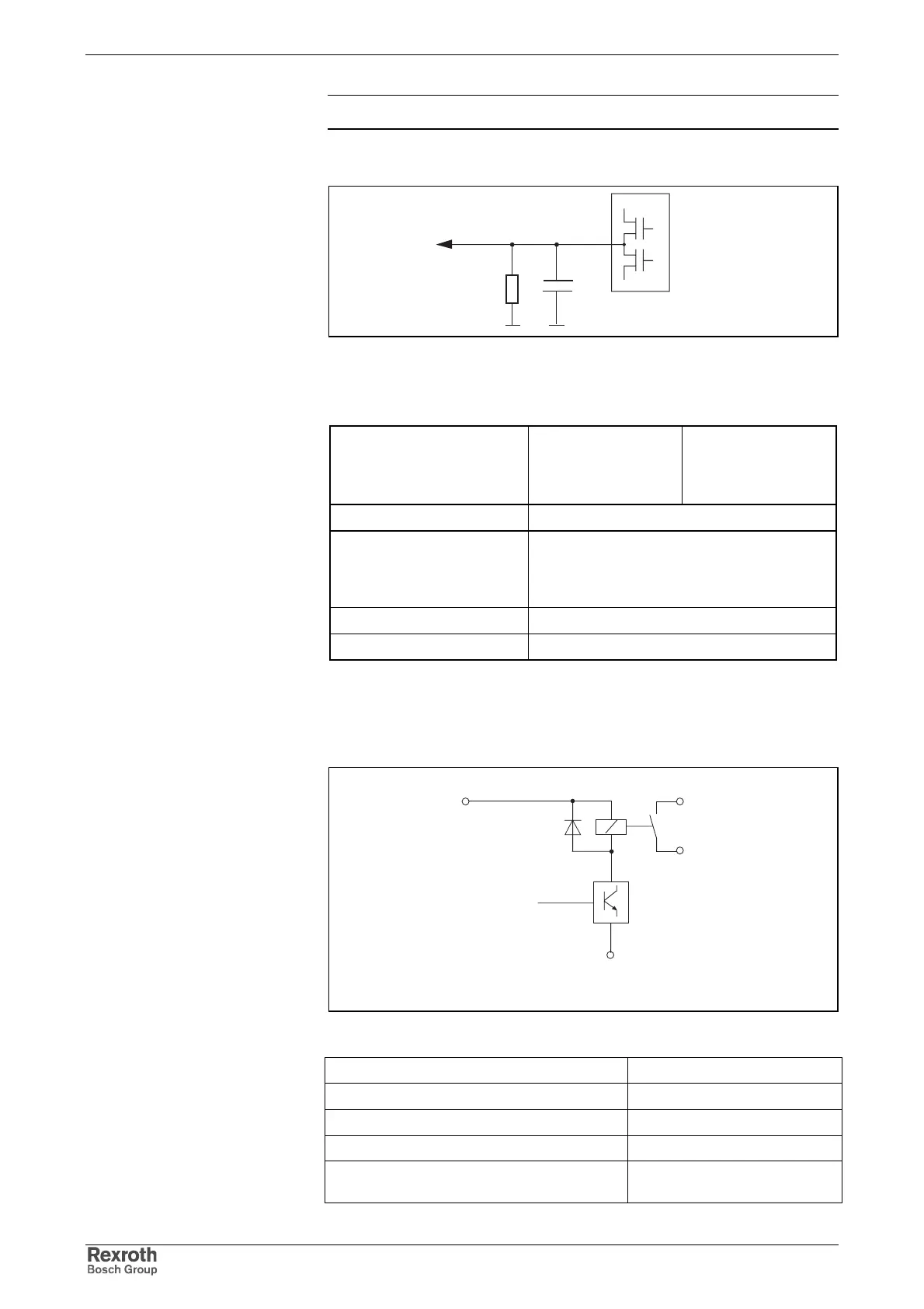
OUT7, OUT8
X5_1_dig_out_prinzip.FH7
R1
C1
R1: 20k
C1: no data
Fig. 5-34: Output circuitry (block diagram)
output voltage:
High
Low
min.
16 V
-0,5 V
max.
24 V
ext
- 1 V
1,5 V
output current I
out
80 mA
rise time / fall time
without load
with load
65 µs / 40 µs
70 µs / 6 µs
overload protection short-circuit proof
electrical isolation optocoupler
Fig. 5-35: Technical Data
Bb1, Bb2
Relais_Bb1_Bb2.fh7
+12V
GND
Bb1
Bb2
Abb. 5-36:Bb1, Bb2 relay
max. switching voltage: DC 40 V
max. switching current: DC 1 A
max. continuous current: DC 1 A
Minimum contact load: 10 mA
Guaranteed number of switching operations at
max. time constant of load < 50 ms:
250,000
Output Circuitry of Digital
Outputs
Technical Data
Loadability of the connection
Bb:
Courtesy of CMA/Flodyne/Hydradyne ▪ Motion Control ▪ Hydraulic ▪ Pneumatic ▪ Electrical ▪ Mechanical ▪ (800) 426-5480 ▪ www.cmafh.com