6-20 Mains and Supply Voltage Connection Rexroth EcoDrive Cs Drives
DOK-ECODR3-DKC**.3-CS*-PR02-EN-P
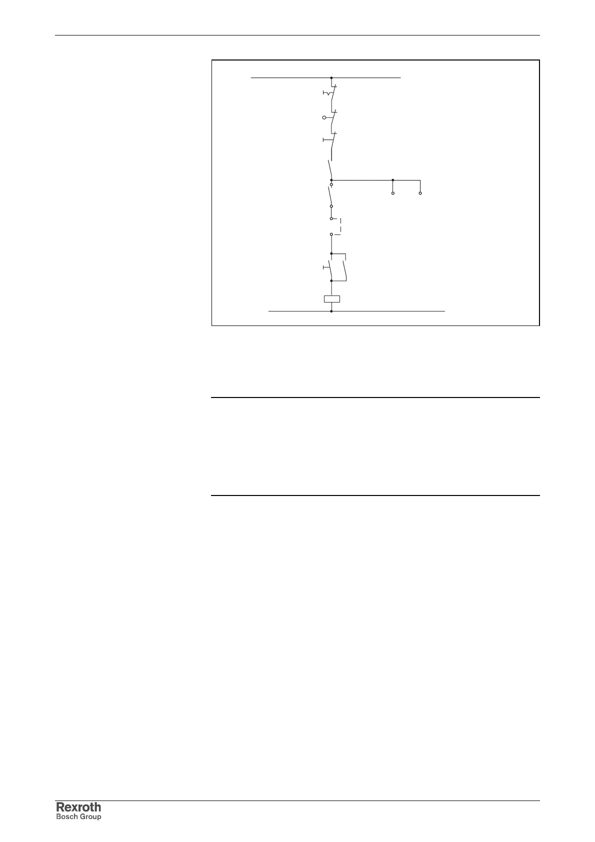
e_stop_schaltung.FH7
K1
1)
K1
Bb
3)
Power off
Power on
Control error
message
Power protection
ext. control voltage +DC 24 V
Safety limit switch
Emergency stop
2)
X5_2/5
X5_2/6
X5_1/6
E- Stop
1): Integrating Bb contacts of more drive controllers in series connection.
(Bb contact: X5_2, Pin 5 and 6);
2): E-stop for more drive controllers on same contactor.
3): Switching power of Bb contact must be noted.
Fig. 6-21: Example of generating the E-stop signal
Note: Do not pick off the E-Stop signal after the Bb contact.
If the safety end switches illustrated also function as a travel
range limit, then a separate set-up must be created in case of
actuation, which makes it possible to move back out of the
end position!
=> See also Functional Description of firmware: "Travel
range limits".
Courtesy of CMA/Flodyne/Hydradyne ▪ Motion Control ▪ Hydraulic ▪ Pneumatic ▪ Electrical ▪ Mechanical ▪ (800) 426-5480 ▪ www.cmafh.com