5-8 Electrical Connections Rexroth EcoDrive Cs Drives
DOK-ECODR3-DKC**.3-CS*-PR02-EN-P
RB1, RB2, RB3: Braking Resistor
Note: The internal braking resistor causes a derating of the
continuous DC bus power. See page 4-12.
By connecting an external braking resistor the derating of the continuous
DC bus power can be prevented.
Note: When an external braking resistor is used, the drive has to be
informed of this fact by means of the DriveTop commissioning
software (call in DriveTop by menu item "Drive Functions ->
Drive controller")
An external braking resistor is available as an accessory.
Data for the internal braking resistor: see chapter 4.4 "Electrical Data"
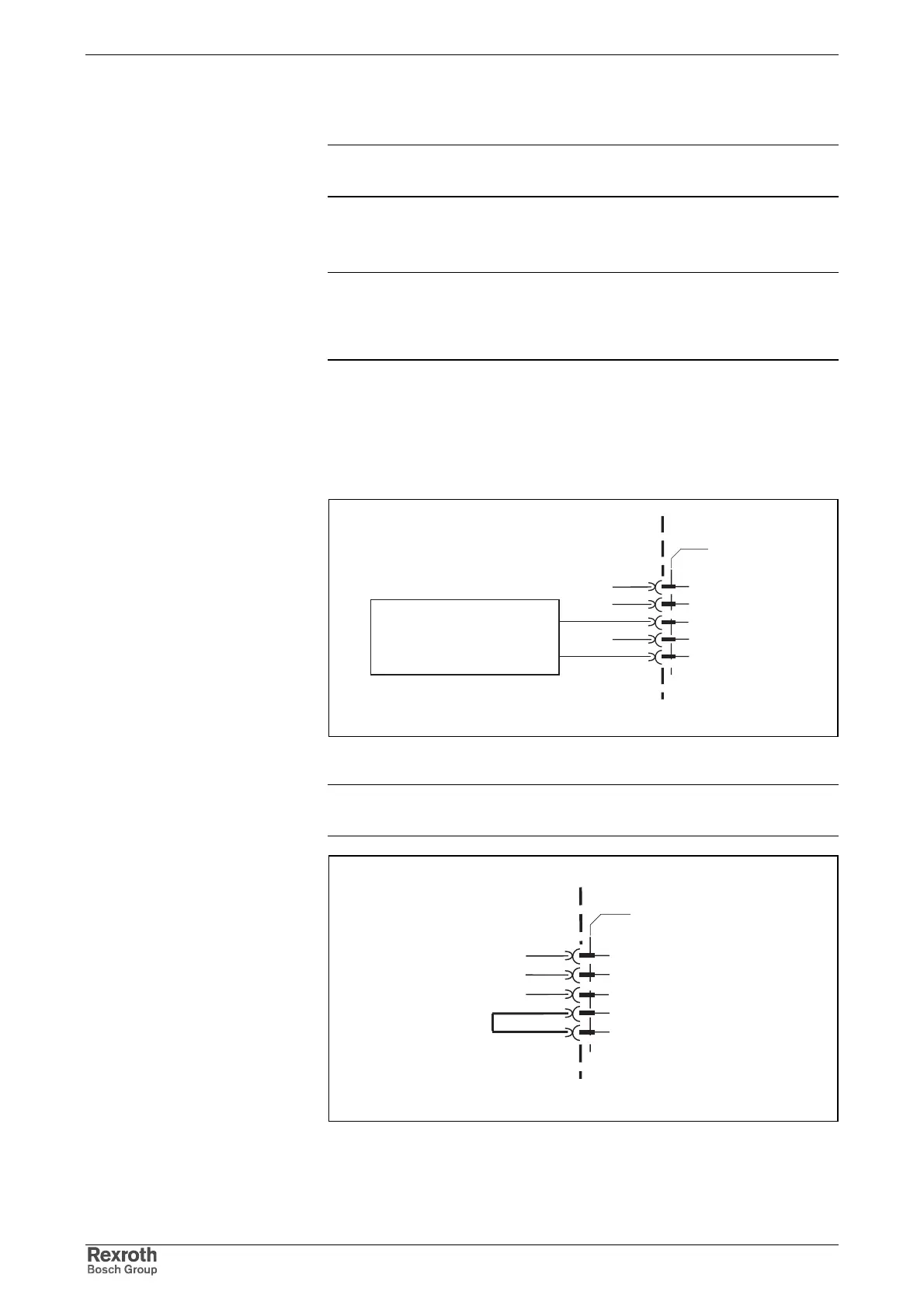
device-external device-internal
X2_RBx_mit_RB.FH7
X2
RB1
RB2
external braking
resistor
Fig. 5-13: Connection for braking resistor
Note: If you do not use any external braking resistor, the RB2 and
RB3 connections must be jumpered.
X2_RBx_ohne_RB.FH7
X2
RB2
RB3
device-external device-internal
Fig. 5-14: Jumper on RB2 and RB3
Accessory
Data
Braking Resistor Connection
Courtesy of CMA/Flodyne/Hydradyne ▪ Motion Control ▪ Hydraulic ▪ Pneumatic ▪ Electrical ▪ Mechanical ▪ (800) 426-5480 ▪ www.cmafh.com