5-34 Electrical Connections Rexroth EcoDrive Cs Drives
DOK-ECODR3-DKC**.3-CS*-PR02-EN-P
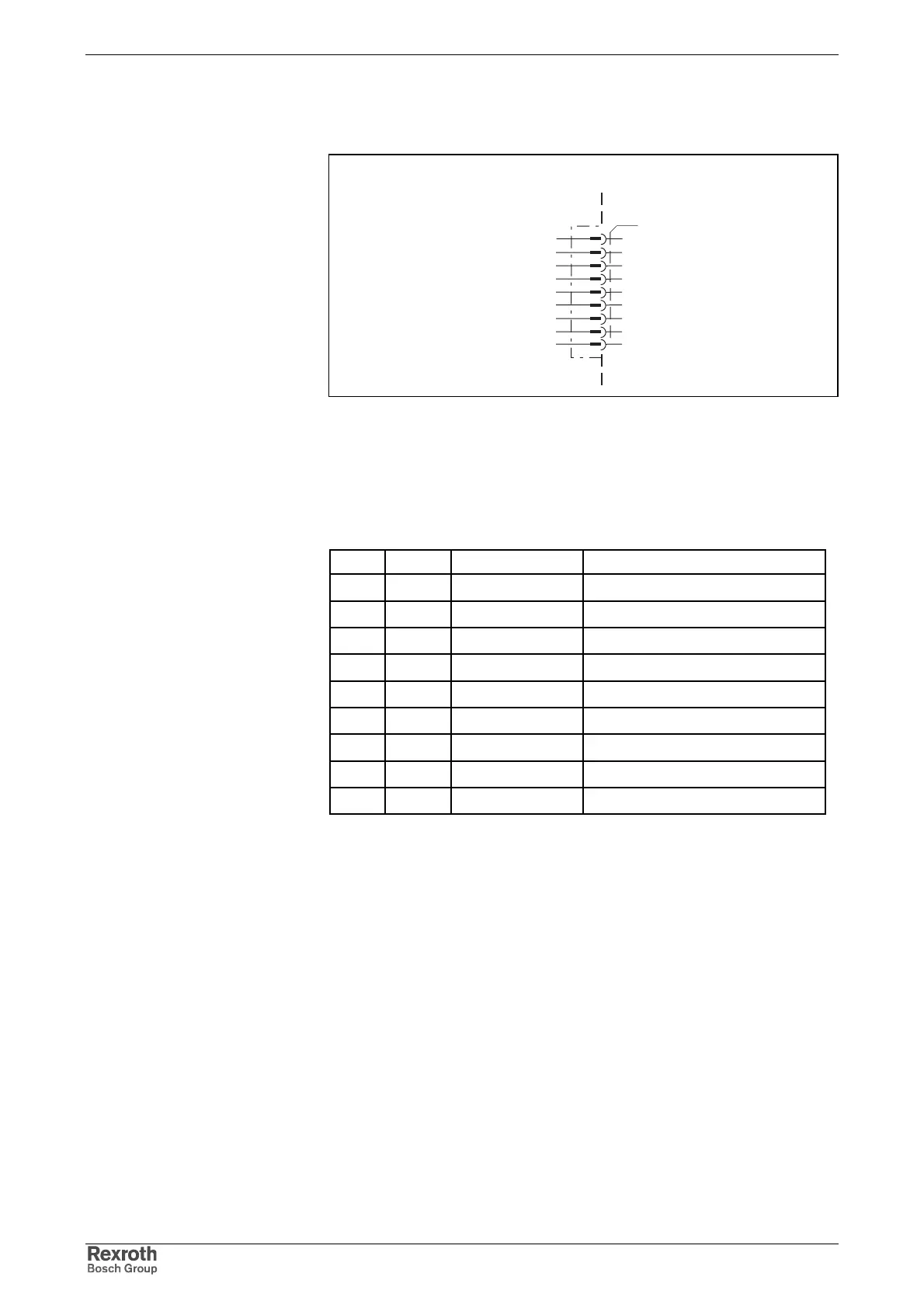
Connection Diagram for Profibus-DP Interface
profibus_anschluss.FH7
Profibus-DP Interface
n.c.
n.c.
B
CNTR-P
BUSGND
VP
n.c.
A
CNTR-N
Repeater control signal P
Busground
Receive/transmit data P
Bus 5 V
Receive/transmit data N
1
2
3
4
5
6
7
8
9
device-external device-internal
Repeater control signal N
Fig. 5-67: Connection
according to DIN EN 50 170
according to DIN EN 50 170 – 2, cable type A
Pin DIR Signal Function
1-- n.c.
2-- n.c.
3 I/O RS485+ receive/transmit data-positive
4 O CNTR-P repeater control signal
50V 0V
6 O +5V repeater supply
7-- n.c.
8 I/O RS485- receive/transmit data-negative
90V 0 V
Fig. 5-68: Signal pin configuration of the connector
Via D-subminiature screws and metallized connector housing.
Connections of Profibus-DP
Interface
Compatibility of the Interface
Recommended Cable Type
Pin Configuration of the Plug-In
Connector
Shield Connection
Courtesy of CMA/Flodyne/Hydradyne ▪ Motion Control ▪ Hydraulic ▪ Pneumatic ▪ Electrical ▪ Mechanical ▪ (800) 426-5480 ▪ www.cmafh.com